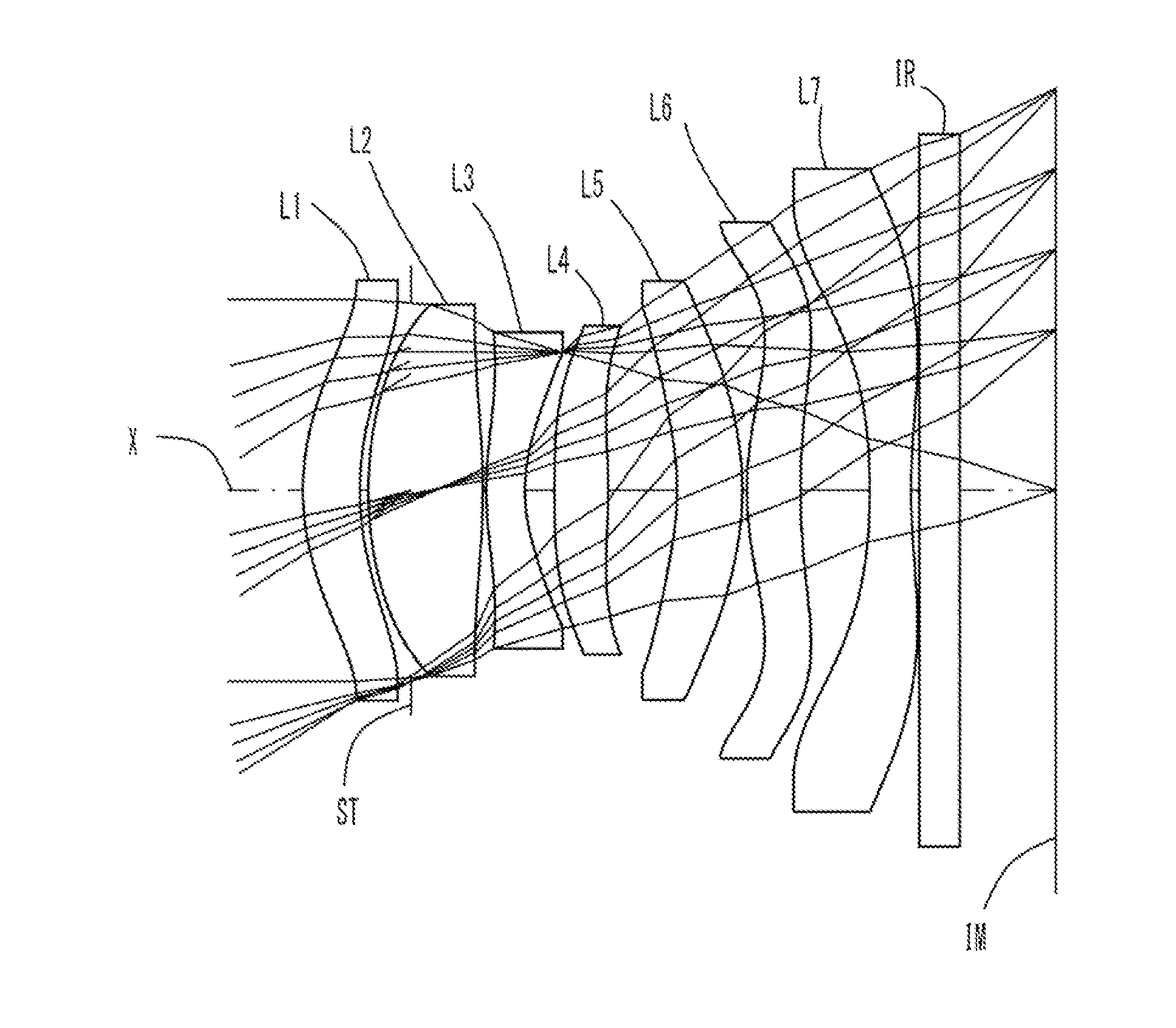
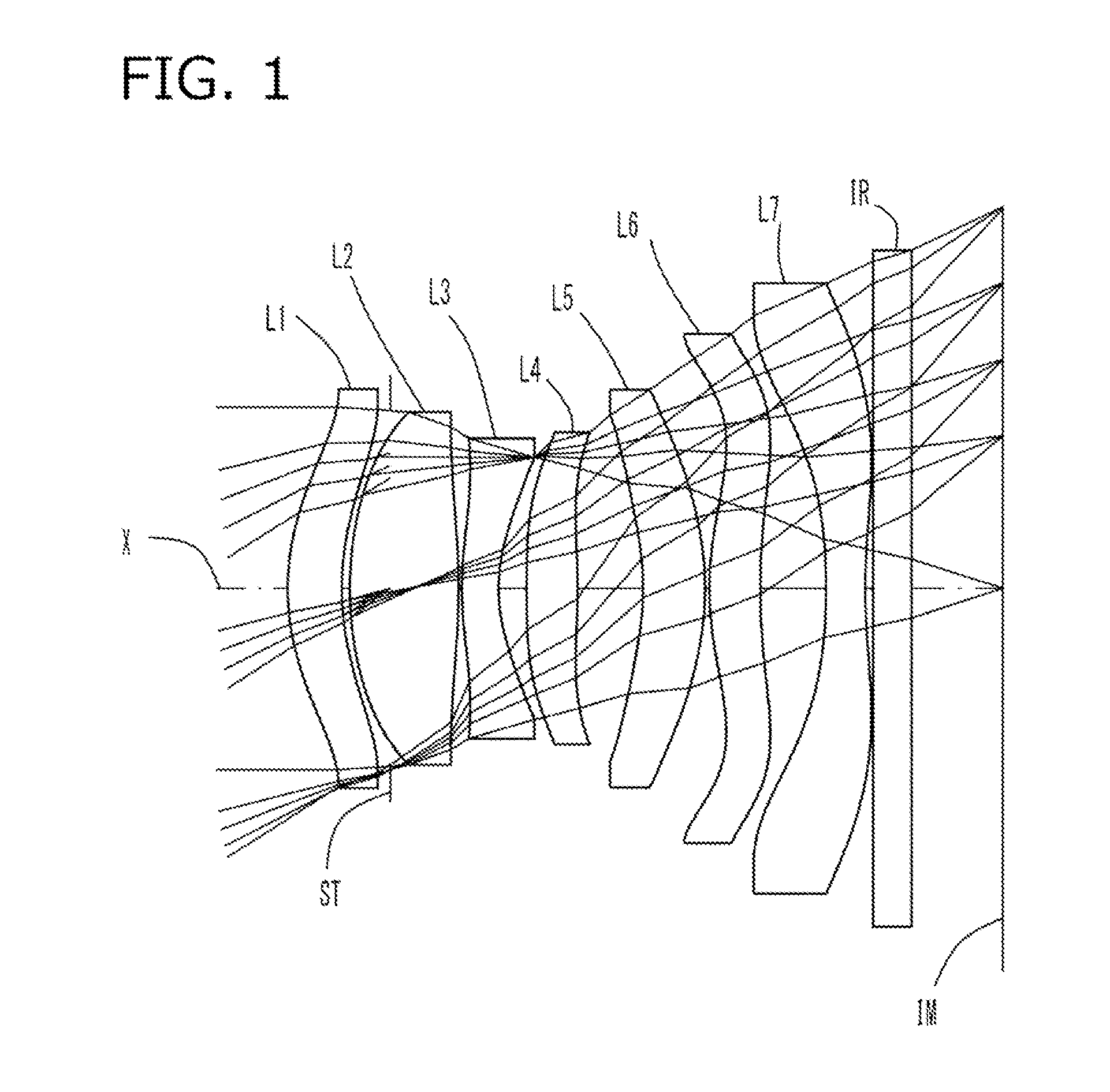
Imaging lens

a technology of imaging lens and spherical lens, applied in the field of imaging lens, can solve the problems of reducing cost and achieving thinness, and achieve the effect of low profil

Active Publication Date: 2014-07-31
TOKYO VISIONARY OPTICS CO LTD
View PDF0 Cites 96 Cited by
  • Summary
  • Abstract
  • Description
  • Claims
  • Application Information

AI Technical Summary

Benefits of technology

[0011]The present invention has been made in view of the above problem and an object thereof is to realize a high-performance lens system which corrects various aberrations pr

Problems solved by technology

Obviously an imaging lens which uses a larger number of constituent lenses provides h

Method used


Image

  • Imaging lens
  • Imaging lens
  • Imaging lens

Examples


example 1

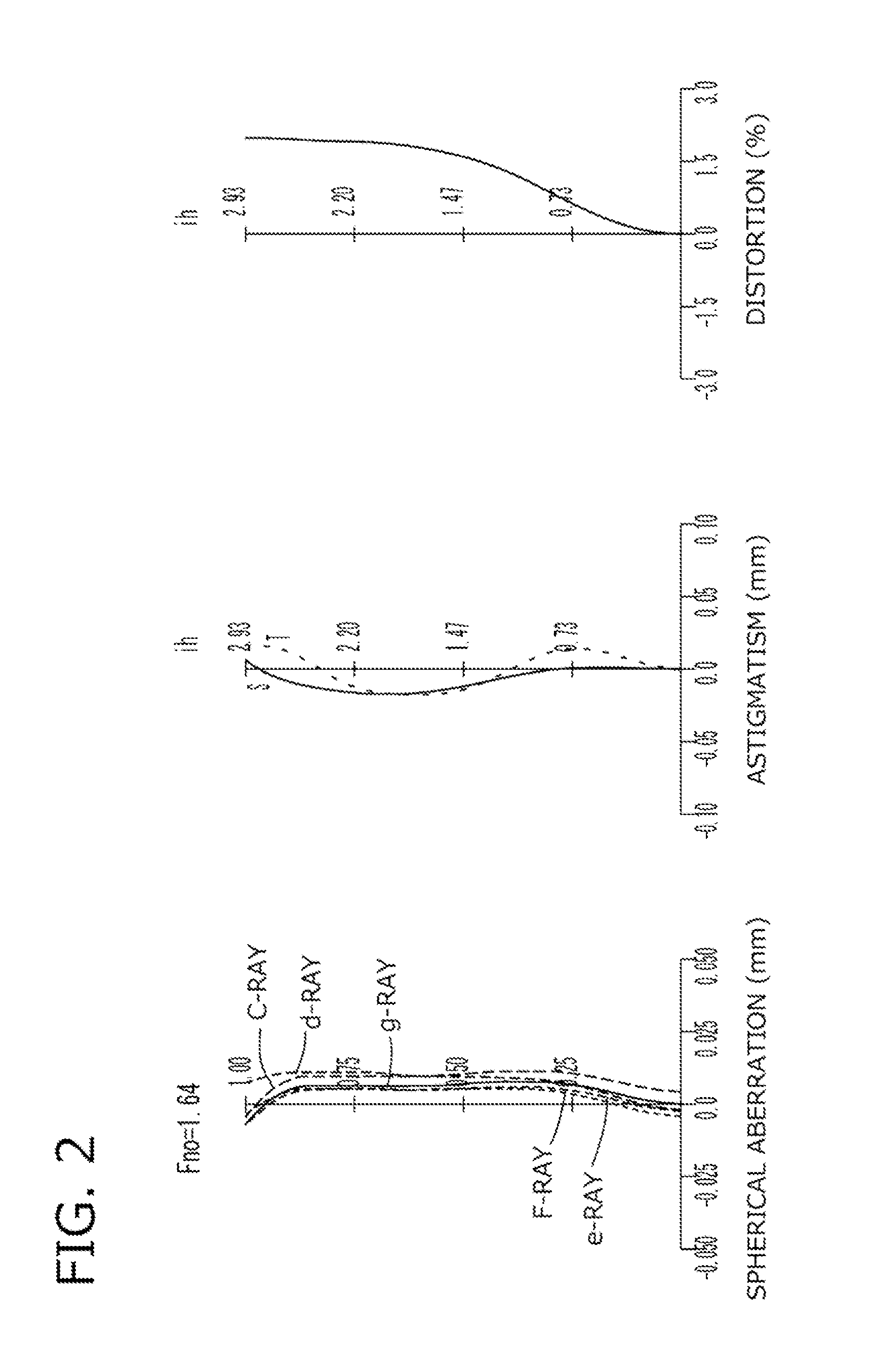
[0078]The basic lens data of Example 1 is shown below in Table 1.

TABLE 1Numerical Example 1 in mmf = 4.54Fno = 1.64ω(deg) = 32.3ih = 2.93TTL = 5.39Surface DataCurvatureSurfaceRefractiveAbbeSurface No. iRadius rDistance dIndex NdNumber νd(Object Surface)InfinityInfinity 1*1.9020.4151.534656.160 2*2.1540.372 3 (Stop)Infinity−0.310 4*2.8040.8351.534656.160 5*−4.6290.025 6*2.6350.2811.635523.911 7*1.2290.215 8*10.7370.3901.534656.160 9*−6.6670.50410*−2.0530.4751.635523.91111*−2.3340.03312*2.3350.3921.543855.57013*5.4440.50414*−4.6820.3001.543855.57015*4.2770.06016Infinity0.3001.516864.19817Infinity0.711Image PlaneInfinityLensStart SurfaceFocal LengthConstituent Lens Data1119.339243.39936−3.930487.754510−78.6866127.201714−4.062Composite Focal Lengthf123.132Aspheric Surface Data1st Surface2nd Surface4th Surface5th Surface6th Surfacek 0.000E+000.000E+000.000E+000.000E+00−2.244E+01A4−2.585E−02−3.053E−02 1.738E−028.350E−02−7.495E−02A6−1.346E−02−1.724E−02 −2.979E−03 −3.576E−02  4.811E−03A8 3....

example 2

[0081]The basic lens data of Example 2 is shown below in Table 2.

TABLE 2Numerical Example 2 in mmf = 4.57Fno = 1.61ω(deg) = 32.3ih = 2.93TTL = 5.38Surface DataCurvatureSurfaceRefractiveAbbeSurface No. iRadius rDistance dIndex NdNumber νd(Object Surface)InfinityInfinity 1*1.9530.4111.534656.160 2*2.2250.346 3 (Stop)Infinity−0.310 4*2.7450.8641.534656.160 5*−4.0890.025 6*2.6620.2901.635523.911 7*1.1910.257 8*10.7370.4041.534656.160 9*−6.6670.54110*−2.0060.4721.635523.91111*−2.2270.02512*2.5620.3931.543855.57013*5.6610.50014*−4.4230.3011.543855.57015*4.2840.06016Infinity0.3001.516864.19817Infinity0.610Image PlaneInfinityLensStart SurfaceFocal LengthConstituent Lens Data1119.597243.21436−3.676487.756510−184.0696128.241714−3.953Composite Focal Lengthf122.984Aspheric Surface Data1st Surface2nd Surface4th Surface5th Surface6th Surfacek 0.000E+000.000E+000.000E+000.000E+00−2.399E+01A4−2.588E−02−3.045E−02 1.627E−028.497E−02−7.432E−02A6−1.344E−02−1.724E−02 −3.376E−03 −3.529E−02  5.948E−03A8 3...

example 3

[0084]The basic lens data of Example 3 is shown below in Table 3.

TABLE 3Numerical Example 3 in mmf = 4.35Fno = 1.61ω(deg) = 33.5ih = 2.93TTL = 5.29Surface DataCurvatureSurfaceRefractiveAbbeSurface No. iRadius rDistance dIndex NdNumber νd(Object Surface)InfinityInfinity 1*1.8110.4351.534656.160 2*2.0610.379 3 (Stop)Infinity−0.310 4*2.9720.7571.534656.160 5*−4.8420.026 6*2.7390.2801.635523.911 7*1.3270.210 8*10.7370.3921.534656.160 9*−6.6670.44310*−2.2880.4831.635523.91111*−2.7410.02512*2.5220.5091.543855.57013*6.6710.49514*−4.7080.3001.543855.57015*4.4580.06016Infinity0.3001.516864.19817Infinity0.611Image PlaneInfinityLensStart SurfaceFocal LengthConstituent Lens Data1117.392243.56536−4.391487.755510−37.2026127.147714−4.163Composite Focal Lengthf123.223Aspheric Surface Data1st Surface2nd Surface4th Surface5th Surface6th Surfacek 0.000E+000.000E+000.000E+000.000E+00−2.079E+01A4−2.541E−02−3.036E−02 1.723E−028.057E−02−7.974E−02A6−1.294E−02−1.835E−02 −7.877E−04 −3.527E−02  8.318E−04A8 2....


PUM


Abstract

A low-cost imaging lens which corrects aberrations properly with a small F-value, ensures high performance with a larger number of constituent lenses and has a more low-profile design than before. The constituent lenses are arranged in the following order from an object side to an image side: a positive (refractive power) first lens having a convex object-side surface near an optical axis; a positive second lens having convex object-side and image-side surfaces near the optical axis; a negative third lens having a concave image-side surface near the optical axis; a fourth lens having at least one aspheric surface; a meniscus fifth lens having a concave object-side surface near the optical axis; a sixth lens as a double-sided aspheric lens; and a negative seventh lens as a double-sided aspheric lens having a concave image-side surface near the optical axis. These constituent lenses are not joined to each other.

Description

[0001]The present application is based on and claims priority of Japanese patent application No. 2013-015291 filed on Jan. 30, 2013, the entire contents of which are hereby incorporated by reference.BACKGROUND OF THE INVENTION[0002]1. Field of the Invention[0003]The present invention relates to imaging lenses which form an image of an object on a solid-state image sensor such as a CCD sensor or C-MOS sensor used in a compact image pickup device and more particularly to imaging lenses which are built in image pickup devices mounted in increasingly sophisticated mobile terminals such as smart phones, mobile phones, and PDAs (Personal Digital Assistants), and game consoles and information terminals such as PCs.[0004]2. Description of the Related Art[0005]In recent years, the market of tablet multifunctional terminals as typified by smart phones has been rapidly expanding and there is a general trend that such terminals incorporate high-performance, high-quality cameras which cope with ...

Claims


Application Information

Patent Timeline
IPC IPC(8): G02B3/04
CPCG02B3/04G02B13/0045G02B9/64G02B27/0025
Inventor ISHIZAKA, TOHRU
Owner TOKYO VISIONARY OPTICS CO LTD
Why Eureka
Try Eureka