Optical pickup and optical information processing apparatus

a technology of optical information processing and optical pickup, which is applied in the direction of optical beam sources, instruments, record information storage, etc., can solve the problems of generating noise, increasing in this kind of aberration, and wavefront degradation caused by such thickness error of transparent substrate, so as to reduce beam diameter, effectively control or reduce the effect of noise generation

Inactive Publication Date: 2007-02-08
RICOH KK
View PDF18 Cites 13 Cited by
  • Summary
  • Abstract
  • Description
  • Claims
  • Application Information

AI Technical Summary

Benefits of technology

[0023] According to the present invention, for these two or three types of optical recording media, i.e., a new blue system, and conventional DVD system and / or CD system, a single object lens and a single aberration correction device are provided by which various types of aberrations occurring mainly due to compatible use of these different types of optical recording media can be effectively controlled, or well reduced. As a result, a satisfactory beam spot can be formed on the optical recording medium in any case with a simple configuration. For example, the divergent state of a beam applied is controlled, a phase shift for canceling out an originally occurring (wavefront / spherical) aberration is provided, or so, whereby the originally occurring aberration can be effectively controlled.
[0032] In this scheme of applying the liquid crystal device for controlling a phase shift provided to a passing beam, by appropriately configuring an arrangement of electrode patterns formed in the liquid crystal device, it is possible also to simplify the electrode pattern, or miniaturize the liquid crystal device. For example, a finite system and an infinite system are used appropriately for different wavelengths, and, thereby, a relevant pupil radius position at which a phase shift should be provided can be controlled differently according to the wavelength. Thereby, a time required for driving the liquid crystal device can be shortened. Further, by setting the pupil radius position at which a phase shirt is provided in a mid point between actually relevant pupil radius positions, the electrode pattern of the liquid crystal device required can be simplified. Furthermore, by applying a finite system for a particular wavelength, this wavelength can be omitted from those for each of which a phase correction is required, and, thus, the electrode pattern can be simplified. Further, whether the required electrode patterns may be formed on one or both of opposite electrodes in the liquid crystal device may be determined according to particular purposes, i.e., electrode pattern simplification, miniaturization of liquid crystal device, or so.

Problems solved by technology

However, when a further improvement in NA of the object lens or the wavelength of the light source is attained, various problems are anticipated.
The anticipated problems include, for example, those caused by a manufacture error of a lens, an even-th aberration which means a distortion in an isotropic wavefront with respect to the optical axis produced according to a manufacture error of a lens applied, a thickness error of a transparent substrate of an optical recording medium loaded, an odd-th aberration which means a distortion in an anisotropic wavefront with respect to the optical axis generated by an inclination of the optical recording medium, or so.
However, when the operating wavelength of 407 nm±10 nm in a light source of a blue wavelength zone is used, the wavefront degradation caused by such a thickness error of the transparent substrate becomes more than 0.07 λ, and, therefore, a some sort of correction becomes required.
From this formula, it can be seen that the shorter wavelength or higher NA results in increase in this sort of aberration.
However, when a light path separation device which does not perform polarization is used, a part of light reflected from the optical recording medium returns to the light source.
In case of using a semiconductor laser as the light source, when a part of reflected light from the optical recording medium returns to the semiconductor laser, the oscillation characteristic of the semiconductor laser is changed, and, thus, there occurs a possibility of generating a noise, at a time of information recording / reproduction / deletion onto the optical recording mediums.
However, in case of using a high output type semiconductor laser in which the oscillation characteristic is likely to change, and, thus, the above-mentioned noise generation may cause a serious problem in an optical pickup also used for information recording.
On the other hand, a manufacture error in products of optical devices, especially, as an object lens, used in an optical pickup may cause a problem concerning an aberration.
Generally, a thickness error, a refractive-index error, a curvature radius error and so forth in the lens may cause generation of the even-th aberration, while a tilt or eccentricity of the lens may cause the odd-th aberration.
Another problem is such that users still have conventional recording medium such as CDs and DVDs.
However, this method may raise the cost or increase the size of the whole machine.
Thus, problems to be solved occurring when achieving an optical pickup directed to future high-density optical recording media are to reduce aberrations which otherwise increase due to increase in NA or reduction in wavelength, and, also, to achieve a compatibility between the conventional standard and new standard optical recording media (i.e., of different generations).
Further, it is also a problem to be solved to achieve these objects without a remarkable increase in size / costs of the machine.
However, in future, in connection with achievement of high-speed rotation of an optical recording medium, application of a multi-layer-type optical recording medium, which will be described later, and also application of a multi-level recording scheme, it may become not possible to tolerate such an aberration matter, and thus, a some special scheme for correcting it should be needed.

Method used


Image

  • Optical pickup and optical information processing apparatus
  • Optical pickup and optical information processing apparatus
  • Optical pickup and optical information processing apparatus

Examples


first embodiment

[0174] Essential features of the present invention will now be described. First, the even-th aberration detection and operation of the correction device when recording, reproduction, or deletion is performed will be described with respect to the blue-system optical recording medium.

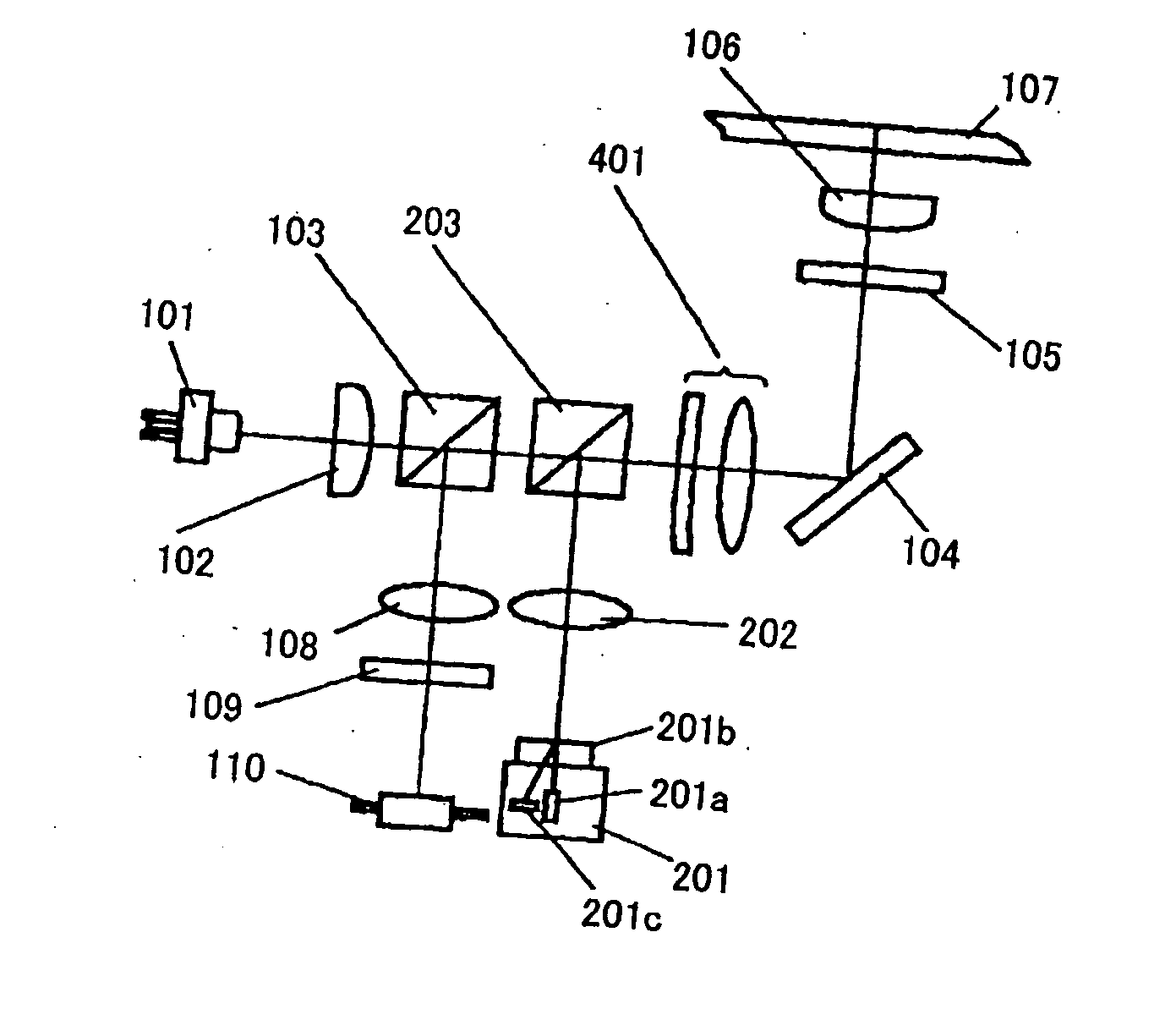
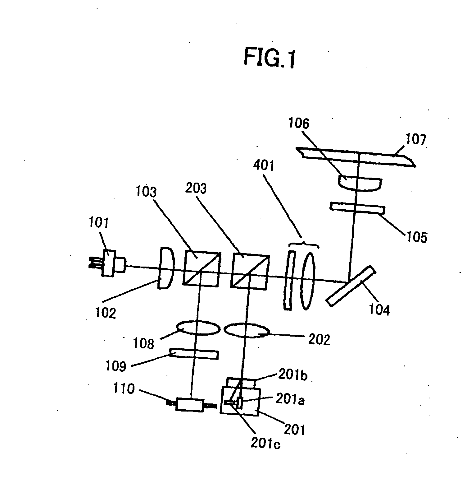
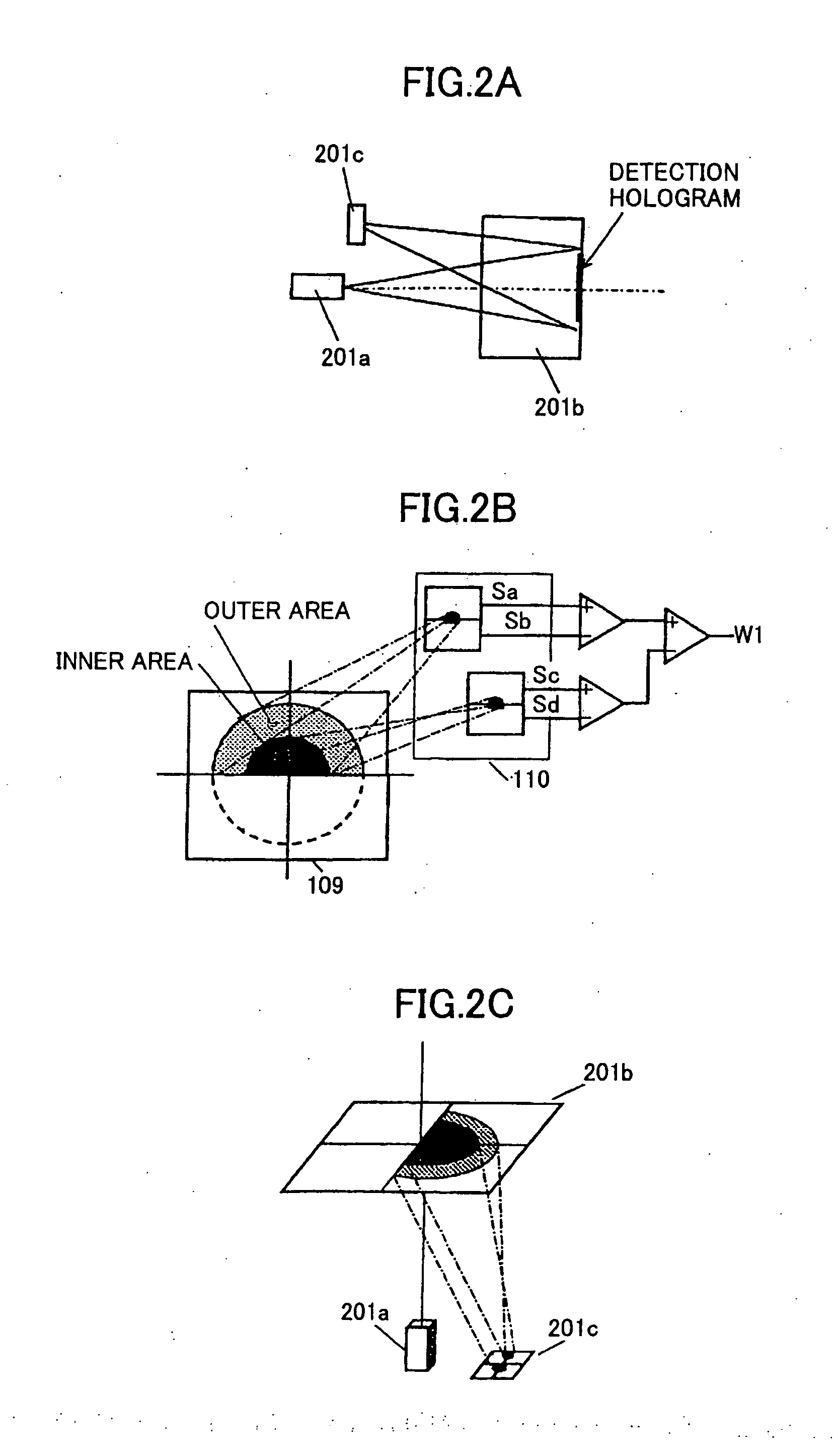
[0175] In FIG. 1, the combination of the beam splitting device 109 and the light-receiving device 110 form ‘the even-th aberration detection device’. As above-mentioned, when a lens manufacture error or a thickness error of an optical recording medium occurs, the even-th aberration may occur, and the form of the optical spot formed on the record surface of the optical recording medium may deteriorate. The thus-occurring aberration may distort the wavefront of the reflected beam, and an aberration occurs in the beam reaching the light-receiving device 110 through the detection lens 108. FIG. 3A shows this state. When the even-th aberration occurs in the returning beam incident onto the detection lens 108, ...

second embodiment

[0194] In the optical pickup a light source with an operating wavelength of a blue wavelength zone of 407 nm, and an object lens with NA: 0.85 are applied for a light-incidence-side substrate having a thickness of 0.1 mm of a blue-system (large storage capacity) optical recording medium, while a light source with an operating wavelength of 660 nm and an object lens with NA: 0.65 are applied for a light-incidence-side substrate with a thickness of 0.6 mm of a DVD-system optical recording medium.

[0195] Differences from the above-described first embodiment are the following two pints: A wavelength selection aperture 204 is added for the object lens 106 for NA: 0.85, and the light-incidence-side substrate having the thickness of 0.1 mm of the optical recording medium 107; and also, a finite DVD's red-system optical system is applied instead of the infinite system such that the incidence beam to the object lens is made to a divergent beam.

[0196] In the second embodiment, when the objec...

fourth embodiment

[0213] The aberration correction device 501 shown in FIG. 6A is realized by the four-axis actuator which controls the optical axis of an object lens 106 not only in the two directions for focus and tracking, but also on other two directions of tilt control. Thereby, the optical axis of the object lens is controlled in an inclination control manner with respect to the general optical axis of the optical system.

[0214] When the inclination of the object lens 106 is changed by this 4-axis actuator as the aberration correction device 501, since the odd-th aberration thus occurs in the beam passing through the aberration correction device 501, the thus-occurring aberration can be used for canceling out the original odd-th aberration to be eliminated. It is assumed that the wavefront aberration which causes the odd-th aberration originating in various kinds of manufacture errors detected by the above-mentioned aberration detection method is such as that shown in FIG. 7B. FIG. 7C shows thi...


PUM


Abstract

An optical pickup performing recording, reproduction and deletion of information onto an optical recording medium, said optical pickup includes light sources of blue wavelength zone, red wavelength zone and infrared wavelength zone; a single object lens which condenses a light from any of the light sources; and a single aberration correction device disposed in a common light path between each of the light sources and the object lens.

Description

BACKGROUND OF THE INVENTION [0001] 1. Field of the Invention [0002] The present invention relates to an optical pickup and an optical information processing apparatus using the optical pickup by which a satisfactory beam spot on an information recording surface of a blue-system optical recording medium which uses a light source of a blue wavelength zone, to an DVD-system optical recording medium using a light source of a red wavelength zone, or to a CD-system optical recording medium using a light source of an infrared wavelength zone. [0003] 2. Description of the Related Art [0004] Optical recording media, such as a CD with a storage capacity of 0.65 GB and a DVD with a storage capacity of 4.7 GB, are spreading as means to store data of image information, voice information, or computer data. Further, demands for a further improvement in recording density and storage capacity become stronger in recent years. Specifically, the necessity for as storage capacity such as for 22 GB by wh...

Claims


Application Information

Patent Timeline
Patent Type & Authority Applications(United States)
IPC IPC(8): G11B7/00G02F1/1343G11B7/12G11B7/125G11B7/13G11B7/135
CPCG02F1/134309G02F2203/18G11B7/1205G11B7/127G11B7/131G11B2007/0013G11B7/1365G11B7/1369G11B7/139G11B7/13925G11B2007/0006G11B7/1353G11B7/123
Inventor HIRAI, HIDEAKI
Owner RICOH KK
Why Eureka
Try Eureka