Battery module and battery module assembly using same

a battery module and battery module technology, applied in secondary cell servicing/maintenance, cell components, vent arrangements, etc., can solve the problems of reducing the size affecting the service life of the battery module, and generating heat to high temperatures for each battery cell. , to achieve the effect of reducing the space for wiring and minimizing the influence of abnormal heat generation

Inactive Publication Date: 2011-08-11
PANASONIC CORP
View PDF4 Cites 79 Cited by
  • Summary
  • Abstract
  • Description
  • Claims
  • Application Information

AI Technical Summary

Benefits of technology

[0014]The present invention provides a battery module capable of reducing space for wiring and of minimizing the influence of abnormal heat generation of a battery cell with failure on the surrounding battery cells, and a battery module assembly using the battery module.
[0016]With this configuration, it is possible to store the battery unit in the storage part of the housing with at least the wiring board and the partition wall in a sealed state. Therefore, even if a battery unit is in an abnormal state, gas, which is ejected by opening of a vent mechanism of a cell, is not supplied with oxygen from the outside, and is exhausted to the outside of the battery module in a state of gas via the through hole of the wiring board. Furthermore, since each battery unit is stored in a partitioned storage part in the housing, heat transfer to the surrounding battery units is suppressed and an influence of the heat can be minimized. Moreover, space necessary for routing power supply wiring, control wiring, or the like, can be considerably reduced by the wiring board. As a result, a battery module having a small size, high safety, and excellent reliability can be achieved.
[0018]According to the present invention, a battery module capable of reducing space for wiring and of minimizing the influence of abnormal heat generation of a battery unit with failure on the surrounding battery units, and a battery module assembly using the battery module can be achieved.

Problems solved by technology

This makes it difficult to reduce the size of the battery module.
Furthermore, as the capacity of battery cells to be stored in a battery module is increased, each battery cell itself may generate heat to high temperatures depending on the mode of use.
At this time the exhausted gas may ignite, so that the gas may produce smoke, or, although rarely, catch fire.
However, in the battery modules described in Patent Literatures 1 and 2, when one cell abnormally generates heat and a safety valve works, an amount of heat of the cell that generates heat or the influence on the surrounding batteries by ignition to the ejected gas cannot be suppressed.
Therefore, the battery units may be deteriorated one after another.
In particular, a battery module in which battery units are mounted has a problem of how to suppress and minimize the expansion of the influence of the battery unit in an abnormal state to the surrounding battery units.
Since the amount of heat generation is increased synergistically as the number of the cells stored in the battery chamber is increased, it is not possible to minimize the influence on the surrounding cells.
Furthermore, since the circuit board is incorporated in resin, reduction in size of the battery module is limited.

Method used


Image

  • Battery module and battery module assembly using same
  • Battery module and battery module assembly using same
  • Battery module and battery module assembly using same

Examples


first exemplary embodiment

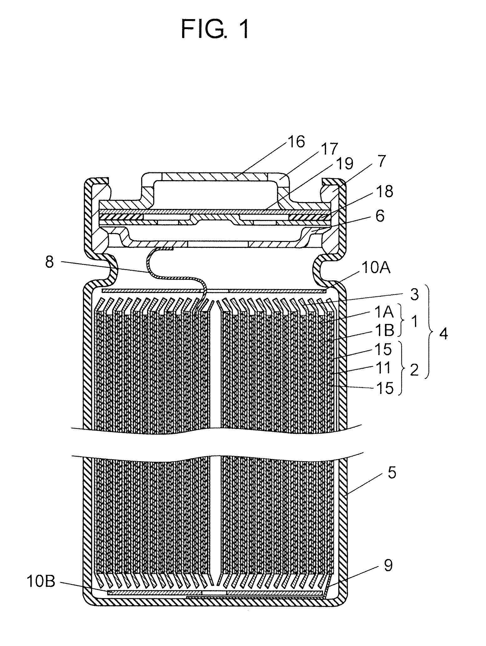
[0048]FIG. 1 is a cross-sectional view of a battery cell constituting a battery unit in accordance with a first exemplary embodiment of the present invention. Hereinafter, even when a battery unit includes only one cell, it is referred to as a battery unit, but for convenience of description, it is also referred to as a battery cell.

[0049]As shown in FIG. 1, a cylindrical battery includes electrode group 4 formed of positive electrode 1, negative electrode 2 and separator 3. To positive electrode 1, positive electrode lead 8 made of, for example, aluminum is connected. Negative electrode 2 faces positive electrode 1. To one end of negative electrode 2, negative electrode lead 9 made of, for example, copper is connected. Separator 3 is interposed between positive electrode 1 and negative electrode 2. In this state, positive electrode 1, negative electrode 2 and separator 3 are wound to form electrode group 4.

[0050]On the top and bottom of electrode group 4, insulating plates 10A and ...

second exemplary embodiment

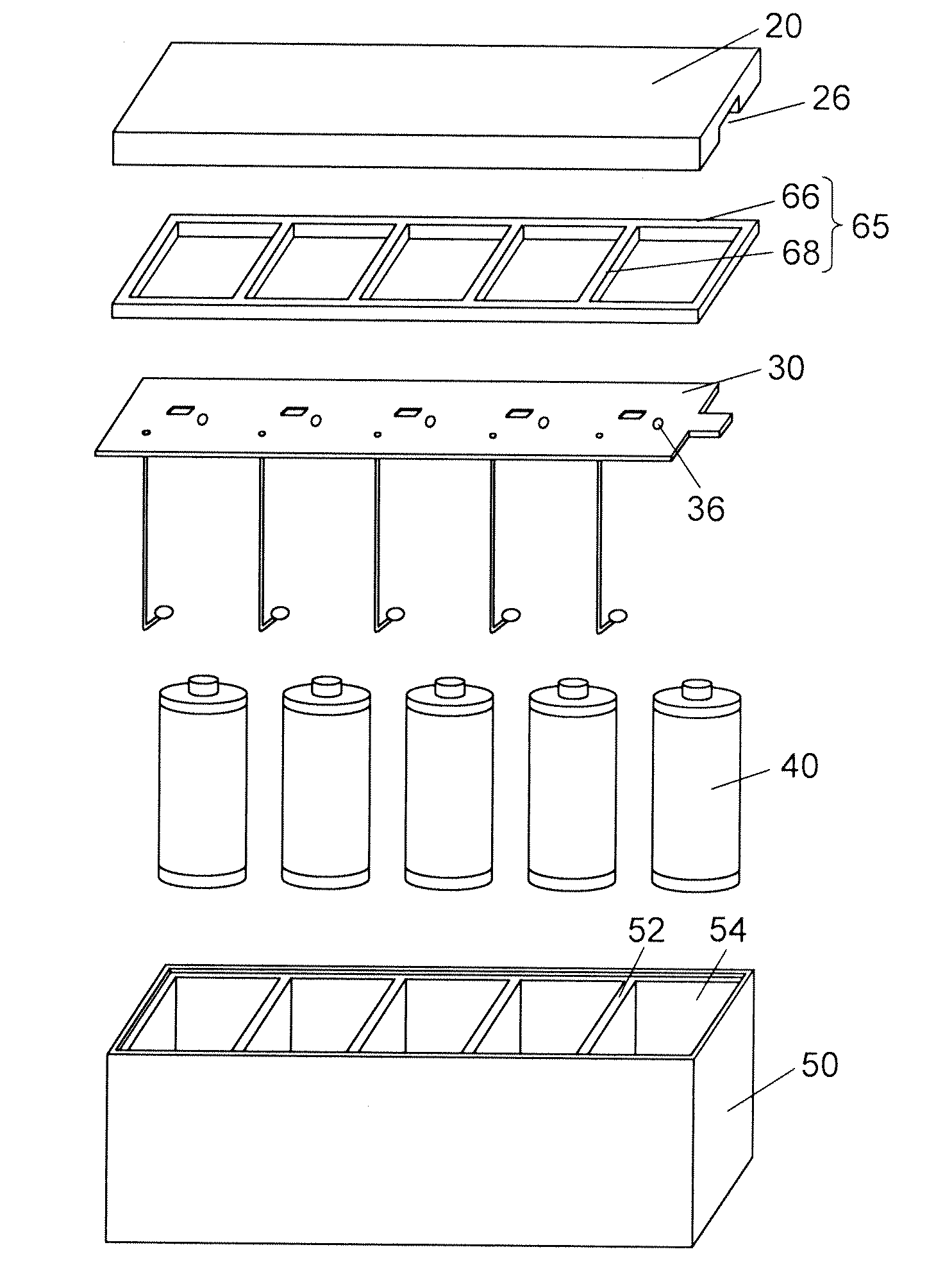
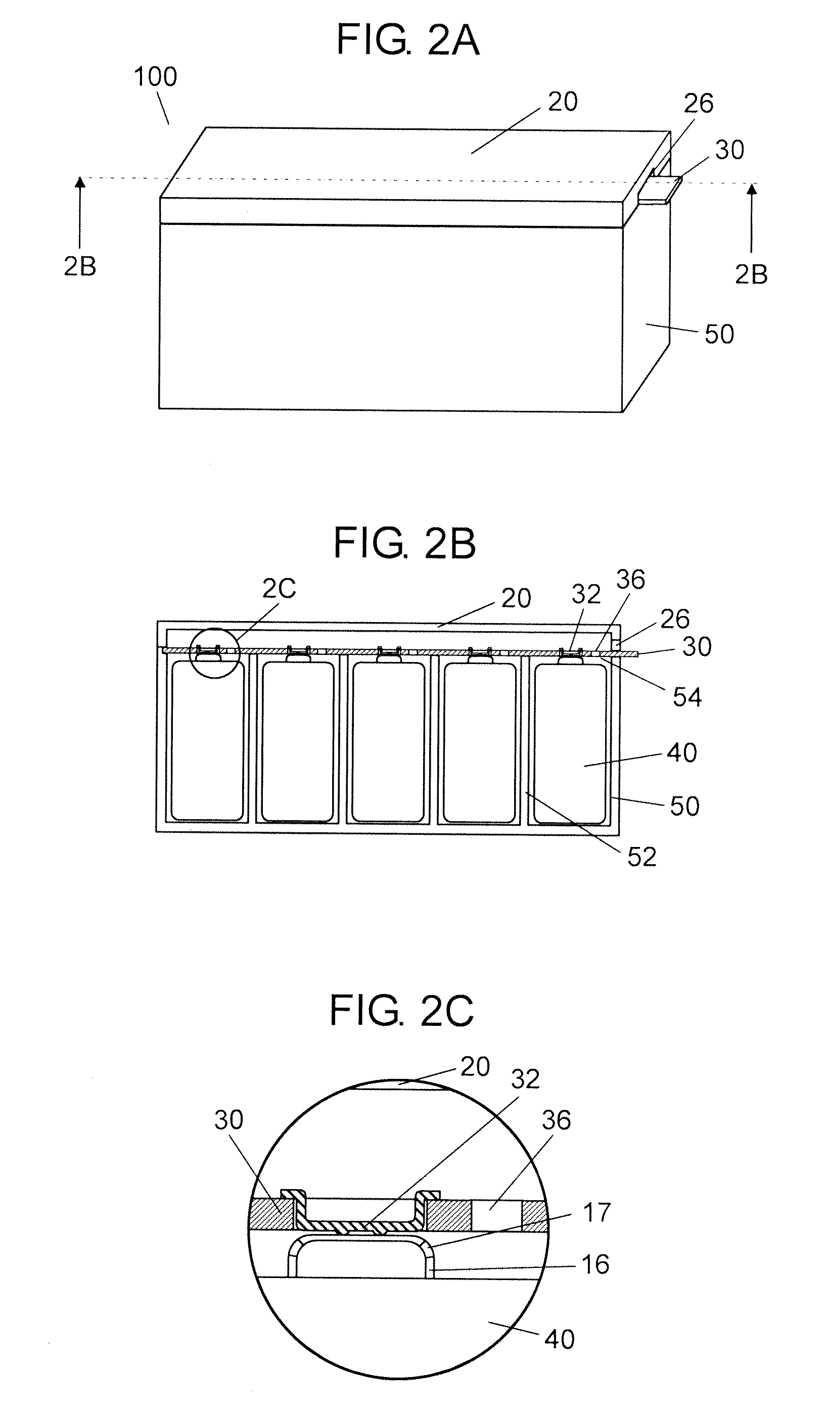
[0077]FIG. 12A is a sectional view of a battery module in accordance with a second exemplary embodiment of the present invention. FIG. 12B is an enlarged sectional view of part 12B in FIG. 12A. Note here that FIG. 12A is a sectional view of a battery module, which corresponds to the sectional view taken along line 2B-2B of FIG. 2A.

[0078]As shown in FIG. 12A, connection terminals 72 having a predetermined shape protrude from wiring board 70 in battery module 200. A predetermined space is provided between wiring board 70 and a first electrode at the vent mechanism side of each battery unit 40. Battery module 200 is different from battery module 100 of the first exemplary embodiment in these points. Note here that since components other than wiring board 70 are the same as those of the first exemplary embodiment, the description thereof is omitted.

[0079]Wiring board 70 formed of, for example, a glass-epoxy substrate includes connection terminals 72, connection plates (not shown), throu...

third exemplary embodiment

[0090]FIGS. 16A and 16B are assembly perspective views showing a battery module assembly in accordance with a third exemplary embodiment of the present invention. Battery module assembly 400 shown in FIG. 16A has a configuration in which four battery modules 100 described in the first exemplary embodiment are arranged and connected by connection member 450. Furthermore, battery module assembly 500 shown in FIG. 16B has a configuration in which two units including two battery modules 100, which is described in the first exemplary embodiment, are piled in two stages longitudinally, and connected by connection member 550. Battery modules 100 are connected in parallel or in series, or combination thereof via connection member 450 or 550.

[0091]According to this exemplary embodiment, depending upon the applications of use, highly versatile battery module assemblies 400 and 500 having arrangement space and necessary voltage and capacity can be configured by arbitrarily combining battery mo...


PUM

PropertyMeasurementUnit
thicknessaaaaaaaaaa
heightaaaaaaaaaa
outer diameteraaaaaaaaaa

Abstract

The battery module includes a plurality of battery units, a housing, a wiring board, and a lid. The battery unit is composed of one or more battery cells each having a vent mechanism. At least one surface of the housing is an open end. The housing has a plurality of storage parts partitioned by one or more partition walls. Each battery unit is stored in each storage part. The wiring board covers the open end of the housing, is disposed at the vent mechanism side of the cell, and has connection terminals connected to the battery units. The lid covers the open end of the housing and the wiring board, and has an open part. Through holes are provided on the wiring board in positions facing the battery units and in a different region from that of the connection terminals.

Description

TECHNICAL FIELD[0001]The present invention relates to a battery module having a structure in which failure such as heat generation occurring in a battery cell does not affect other cells, and a battery module assembly using the battery module.BACKGROUND ART[0002]Recently, from the viewpoint of resource savings and energy savings, secondary batteries such as nickel hydrogen secondary battery, nickel cadmium secondary battery and lithium ion secondary battery, which can be used repeatedly, are increasingly demanded. Among them, the lithium ion secondary battery has light weight, high electromotive force, and large energy density. Therefore, demand for lithium ion secondary batteries is increased as driving power sources for various portable electronic apparatuses and mobile telecommunication apparatuses such as portable telephones, digital cameras, video cameras, notebook-sized personal computers and the like.[0003]On the other hand, in order to reduce the amount of fossil fuel to be ...

Claims


Application Information

Patent Timeline
Patent Type & Authority Applications(United States)
IPC IPC(8): H01M2/12H01M2/10H01M10/48H01M50/213H01M50/227H01M50/271H01M50/284H01M50/289H01M50/502H01M50/51H01M50/512
CPCH01M2/0242H01M2/1016H01M2/1077H01M2/12H05K1/0272H01M10/42H01M10/4207H01M10/425H01M10/482H01M2/202Y02E60/10H01M50/30H01M50/502H01M50/284H01M50/213H01M50/512H01M50/51H01M50/227H01M50/271H01M50/289H01M50/20
Inventor YASUI, SHUNSUKENAKASHIMA, TAKUYAHIRAKAWA, YASUSHIASAKURA, JUN
Owner PANASONIC CORP
Why Eureka
Try Eureka