Robotic endoscope with wireless interface

a robotic endoscope and wireless interface technology, applied in the field of robotic endoscopes, can solve the problems of wasting a lot of time, wasting a lot of resources, so as to reduce the number of endoscopes, reduce the time, equipment, and the floor space required

Inactive Publication Date: 2005-03-24
BOSTON SCI SCIMED INC
View PDF51 Cites 151 Cited by
  • Summary
  • Abstract
  • Description
  • Claims
  • Application Information

AI Technical Summary

Benefits of technology

[0020] The advantages of the present invention are numerous and include a reduction in endoscope inventory as well as...

Problems solved by technology

Even after 20 years of refinement, present day endoscopes for gastroenterology are complex and costly.
Moreover, the endoscopes are typically washed and disinfected, by hand labor and in expensive washing machines...

Method used


Image

  • Robotic endoscope with wireless interface
  • Robotic endoscope with wireless interface
  • Robotic endoscope with wireless interface

Examples


Embodiment Construction

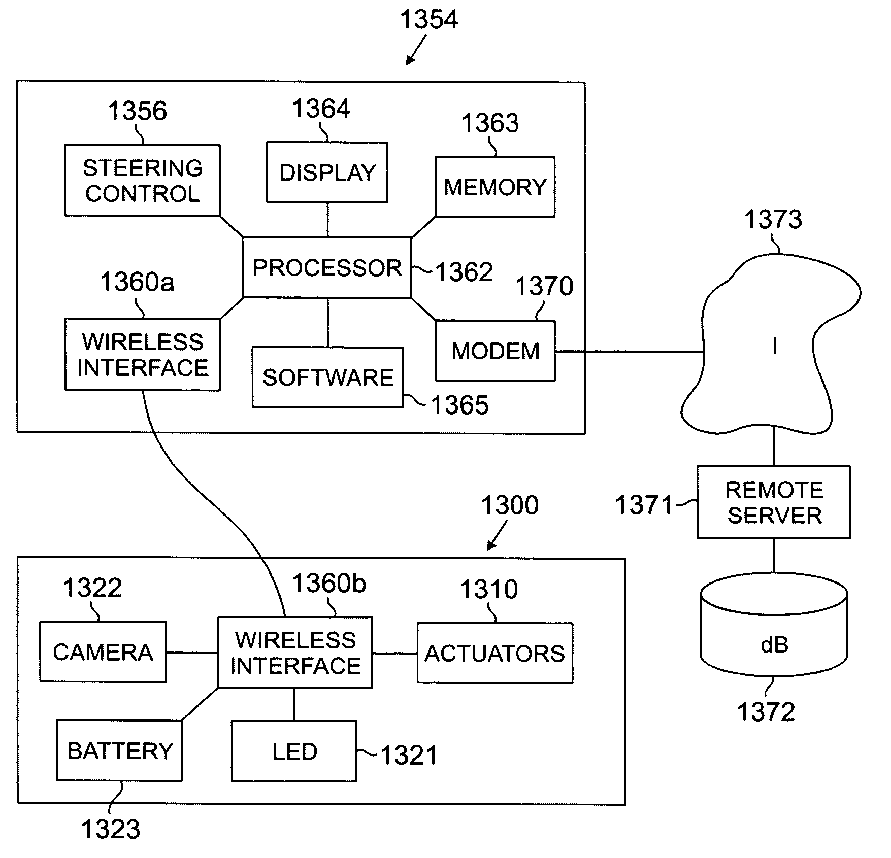
[0035] Referring now to FIG. 14, according to a preferred embodiment of the invention, an endoscope portion 1400 is constructed as an elongated body that contains numerous electronic actuators (not illustrated), which are controlled by a control and display unit such as a computer 1454.

[0036] The working tip 1403 of the endoscope portion 1400, which is encircled by area A in FIG. 14 and is illustrated in more detail in FIG. 11, has a sensing system that senses the body lumen. More specifically, referring now to FIG. 11, the particular working tip 1103 illustrated has a sensing system that includes an energy source 1121 (e.g., a light source) and an imaging subsystem 1122 (e.g., an imaging detector such as a camera). A working channel 1120 is also illustrated in FIG. 11.

[0037] Referring again to FIG. 14, a power source (not shown), a wireless interface including drivers (not shown), and a working channel 1420 are provided at the proximal end of the endoscope portion 1400. The wirel...


PUM


Abstract

An endoscope apparatus and method of operating the same. The endoscope apparatus comprises an endoscope portion and a control and display unit. The endoscope portion preferably comprises: (i) a sensor disposed at a distal end of the endoscope portion and providing endoscope data; (ii) one or more electronically controlled actuators (e.g., electroactive polymer actuators) controlling the operation of the endoscope portion based on received control signals; (iii) a first wireless transceiver coupled to the sensor and the one or more electronically controlled actuators, transmitting received endoscope data from the sensor and forwarding received control signals to the one or more electronically controlled actuators; and (iv) a portable power source (e.g., a battery) coupled to the sensor, the first wireless transceiver, and the one or more electronically controller actuators. The control and display unit preferably comprises: (i) a second wireless transceiver coupled via a wireless link to the first transceiver in the endoscope portion and receiving endoscope data from the first transceiver and transmitting control signals to the first transceiver; (ii) a control portion coupled to the second wireless transceiver and sending control signals to the one or more actuators in the endoscope portion via the first and second wireless transceivers; and (iii) a display portion that displays information received from the sensor via the first and second wireless transceivers. Another aspect of the present invention is directed to a method for providing single-use endoscopes to one or more hospitals.

Description

STATEMENT OF RELATED APPLICATION [0001] This application is a continuation and claims the benefit of priority to co-pending U.S. patent application Ser. No. 10 / 177,491, filed Jun. 21, 2002, entitled “Robotic Endoscope With Wireless Interface,” which is a continuation-in-part of U.S. Ser. No. 09 / 971,419, filed Oct. 5, 2001, entitled “Robotic Endoscope.” Both of the afore-mentioned prior applications are incorporated by reference herein in their entireties.FIELD OF THE INVENTION [0002] The present invention relates to robotic endoscopes, and more particularly to robotic endoscopes that are adapted for remote control. BACKGROUND OF THE INVENTION [0003] Diagnostic endoscopy is a common procedure in the United States and other countries, perhaps being second only to interventional cardiology in generating hospital revenue. [0004] Traditional endoscopy typically utilizes flexible endoscopes that are steered by internal tension wires. These probes typically include means for illumination, ...

Claims


Application Information

Patent Timeline
IPC IPC(8): G02B23/24A61B1/00A61B1/005A61B1/05G16H40/63G16Z99/00
CPCA61B1/00059A61B1/00103A61B1/0053A61B1/0055A61B1/0058G06Q50/28A61M2025/0058G06F19/3406G06Q10/06G06Q10/08G06Q50/22A61B1/2736G16H40/63G16Z99/00
Inventor BANIK, MICHAEL S.COUVILLON, LUCIEN ALFRED JR.
Owner BOSTON SCI SCIMED INC
Why Eureka
Try Eureka