Modular kerfing drill bit

Inactive Publication Date: 2006-09-07
GEN ELECTRIC CAPITAL +2
View PDF7 Cites 61 Cited by
  • Summary
  • Abstract
  • Description
  • Claims
  • Application Information

AI Technical Summary

Benefits of technology

[0017] Another advantage of the present invention is that it provides a hybrid bit design that is modular, permitting reduced inventories of component parts for assembly of multiple configurations of drill bits. Another advantage of the present invention is that it provides a hybrid bit design that can be assembled quickly, making the finished product deliverable faster than prior art designs. Another advantage of the present invention is that it provides a hybrid drill bit design that incorporates larger component cutting elements and larger bearing and seal systems which is more durable and drills faster.
[0018] Another advantage of the present invention is that it provides a hybrid drill bit design having very large flow relief area between the kerfing segments, allowing the bit to perform at very high rates of penetration without cutting build-up and balling of the bit. Other advantages of the present invention will become apparent from the following descriptions, taken in connection with t

Problems solved by technology

As the roller cone cutters roll on the bottom of the hole being drilled, the teeth or carbide inserts apply a high compressive load to the rock and fracture it.
When drilling rock with a roller cone cutter, the fracture effect of loading on the teeth of the rock bed is limited due to the rock matrix surrounding the borehole.
Thus, it appears in usual drilling operations that small cracks are created in the rock, which return to the surface of the bottom of the wellbore creating chips instead of propagating deep into the rock itself.
Thus, the bit tooth of the usual rock bit presses on the rock surface tending to create small cracks which propagate downward, but by virtue of the resistance to fracture offered by the surrounding rock matrix, a crack follows the path of least resistance and emerges at the surface on the bottom of the wellbore, thus creating the small chips.
This bit design causes rapid failure of the drag cutters, however, since virtually all the drilling fluid escapes through the windows and results in insufficient fluid flow to cool the drag bit component.
A primary disadvantage of the prior art designs is that they are extremely difficult and expensive to manufacture.
Due to the extremely high cost of manufacturing the prior art designs, they have proven to be inefficient in a cos

Method used


Image

  • Modular kerfing drill bit
  • Modular kerfing drill bit
  • Modular kerfing drill bit

Examples


Example

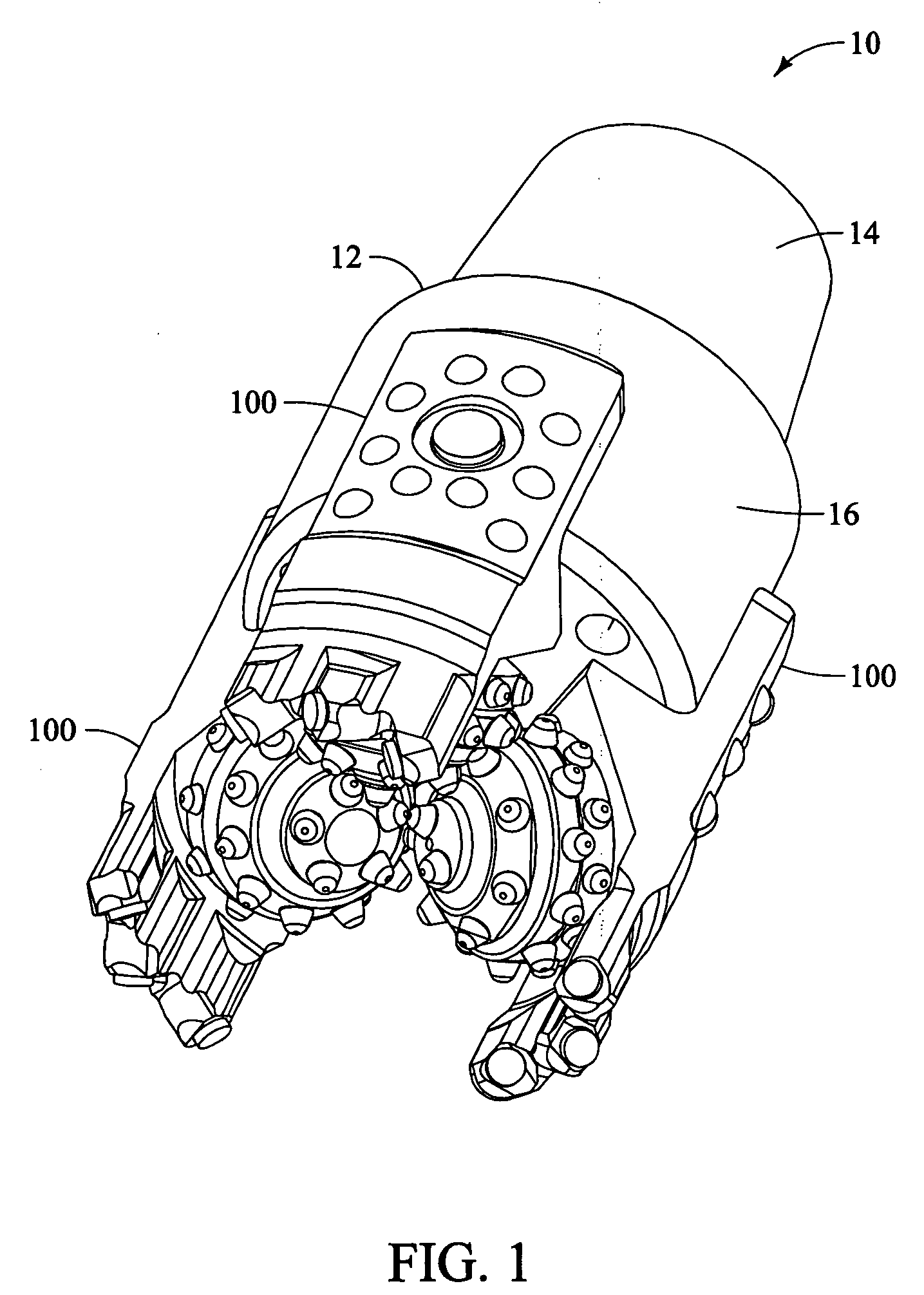
[0035]FIG. 1 is an isometric view of a preferred embodiment of the present invention for a Modular Kerfing Drill Bit 10. In the embodiment shown, drill bit 10 has a body 12. Body 12 has a connection 14 for attachment to a drill string member (not shown). Body 12 has a base 16 below connection 14 and contiguous thereto. Cutter assemblies 100 are shown attached to body 12.

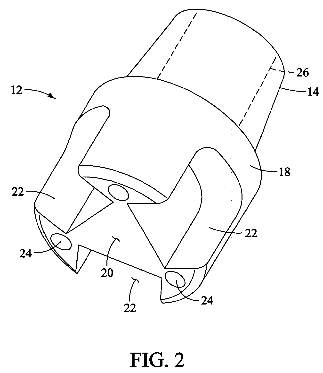
[0036]FIG. 2 is an isometric view of a preferred embodiment of bit body 12 of the present invention, shown with cutter assemblies 100 unattached. In this view, it is seen that base 16 has a generally cylindrical outer portion 18 and a bottom 20. Slots 22 are formed in base 16, and intersect both outer portion 18 and bottom 20. Slots 22 are formed for secure location of cutter assemblies 100. Also in body 12, ports 24 are provided, and interconnect to internal passage 26 (dashed line).

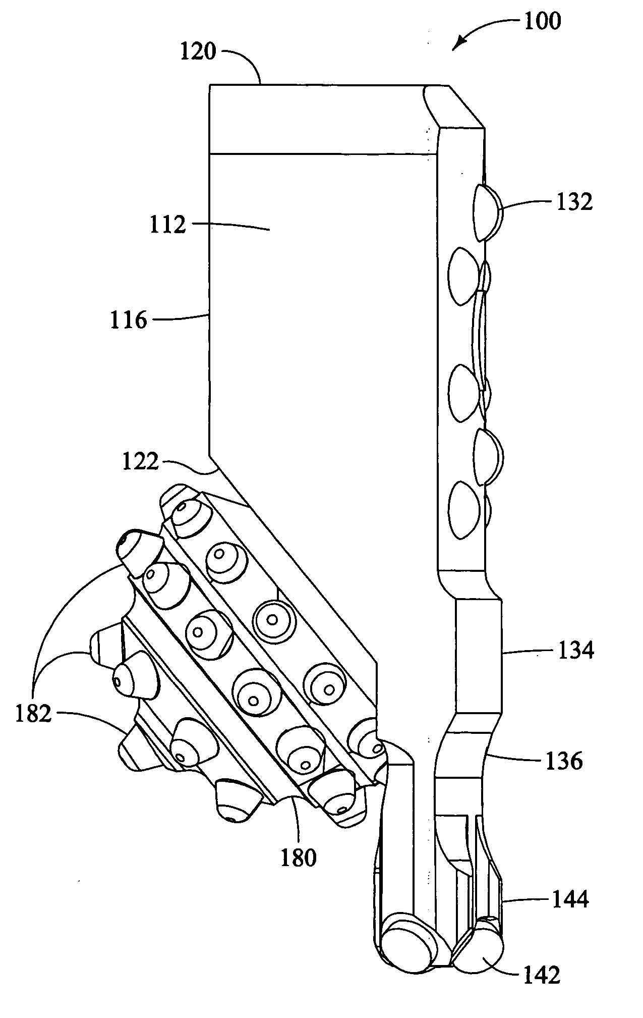
[0037]FIG. 3 is an isometric view of a preferred embodiment of a cutter assembly 100. Cutter assembly 100 has a leg 110. Leg 110 has ...


PUM


Abstract

A modular kerfing rock drilling bit (10) is presented. Drill bit (10) comprises a bit body (12) having a connection (14) for attachment to a drill string member. A base portion (16) below the connection (14) has an outer portion (18) and a bottom (20). Slots (22) are formed in the base portion (16). A cutter assembly (100) comprises a leg (110) insertable into the slot (22) of the bit body (16). A journal (126) extends angularly downward and inward from the leg (110) for bearing support of a cone (180) rotatably mounted on the journal (126). A plurality of cutters (182) extend outward from the surface of the cone (180). A kerfing segment (140) extends downward from the leg (110) beyond the cone (180). A plurality of kerf cutters (142) are attached to the bottom of the kerfing segment (140).

Description

CROSS REFERENCE TO RELATED APPLICATION [0001] None. BACKGROUND OF THE INVENTION [0002] 1. Technical Field [0003] The present invention relates generally to drilling bits used for drilling earth formations. More specifically, the present invention relates to a novel modular design for the improved construction of kerfing type rock bits, comprised of a combination of fixed cutters and roller cone cutters. [0004] 2. Description of Related Art [0005] In the exploration of oil, gas, and geothermal energy, drilling operations are used to create boreholes, or wells, in the earth. These operations normally employ rotary and percussion drilling techniques. In rotary drilling, the borehole is created by rotating a tubular drill string with a drill bit secured to its lower end. As the drill bit deepens the hole, tubular segments are added to the top of the drill string. While drilling, a drilling fluid is continually pumped into the drilling string from surface pumping equipment. The drilling ...

Claims


Application Information

Patent Timeline
IPC IPC(8): E21B10/00
CPCE21B10/04
Inventor ESTES, ROYGEARHART, MARVINCASTLE, JOHNNY
Owner GEN ELECTRIC CAPITAL
Why Eureka
Try Eureka