Pin retainer for fiber optic connector and associated fabrication method

a technology of fiber optic connectors and retainers, which is applied in the direction of optical elements, coupling device connections, instruments, etc., can solve the problems of time-consuming and labor-intensive process of gluing guide pins to e-ferrules, and the inability to convert the female configuration of mt-rj or mtp connectors to the male configuration, so as to reduce the inventory of different fiber optic connectors and achieve high efficiency

Inactive Publication Date: 2006-05-02
CORNING OPTICAL COMM LLC
View PDF10 Cites 61 Cited by
  • Summary
  • Abstract
  • Description
  • Claims
  • Application Information

AI Technical Summary

Benefits of technology

[0018]An improved guide pin retainer for a fiber optic connector according to the present invention permits guide pins to be inserted following the assembly of the connector and the polishing of the front face of the ferrule. Thus, the pin retainer permits guide pins to be inserted in the field from the front face of the ferrule in order to convert a female configuration of a fiber optic connector to a male configuration, thereby reducing the inventory of different fiber optic connectors that must be carried by a field technician. Moreover, pin retainers according to the present invention are no larger in cross-sectional dimensions than the ferrule and do not extend rearward beyond the ferrule. Furthermore, pin retainers according to the invention generate a pin retention that preferably exceeds at least about 8 lbs, and more preferably, at least about 10 lbs. Still further, pin retainers according to the present invention are capable of being fabricated by a highly efficient wire EDM process that permits a large quantity of the pin retainers to be produced in an automated environment with little or no operator involvement. Finally, pin retainers according to the present invention may be positioned on a feature that may be machined, but preferably is molded, onto an exterior surface of the ferrule.

Problems solved by technology

Thus, the guide pins of the male configuration of an MT-RJ or MTP connector must be inserted during the pre-assembly of the ferrule in the factory and cannot be inserted in the field once the remainder of the connector has been assembled around the ferrule.
As a result, the female configuration of an MT-RJ or MTP connector cannot be converted to a male configuration in the field by merely inserting guide pins through the guide pins holes defined by the MT ferrule since the guide pins will not be appropriately grasped by the pin keeper.
Generally, MT-RJ and MTP connectors also cannot be pre-assembled.
Unfortunately, the process of gluing the guide pins to the E-ferrule is a time-consuming operation and must be carefully performed to prevent any epoxy from reaching the front face of the ferrule.

Method used


Image

  • Pin retainer for fiber optic connector and associated fabrication method
  • Pin retainer for fiber optic connector and associated fabrication method
  • Pin retainer for fiber optic connector and associated fabrication method

Examples


Embodiment Construction

[0038]The present invention now will be described more fully hereinafter with reference to the accompanying drawings, in which preferred embodiments of the invention are shown. This invention may, however, be embodied in many different forms and should not be construed as limited to the embodiments set forth herein; rather, these embodiments are provided so that this disclosure will be thorough and complete, and will fully convey the scope of the invention to those skilled in the art. Like numbers refer to like elements throughout.

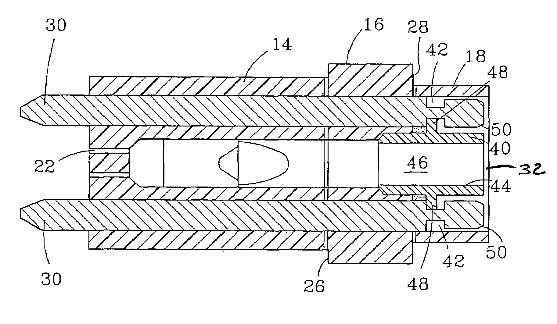
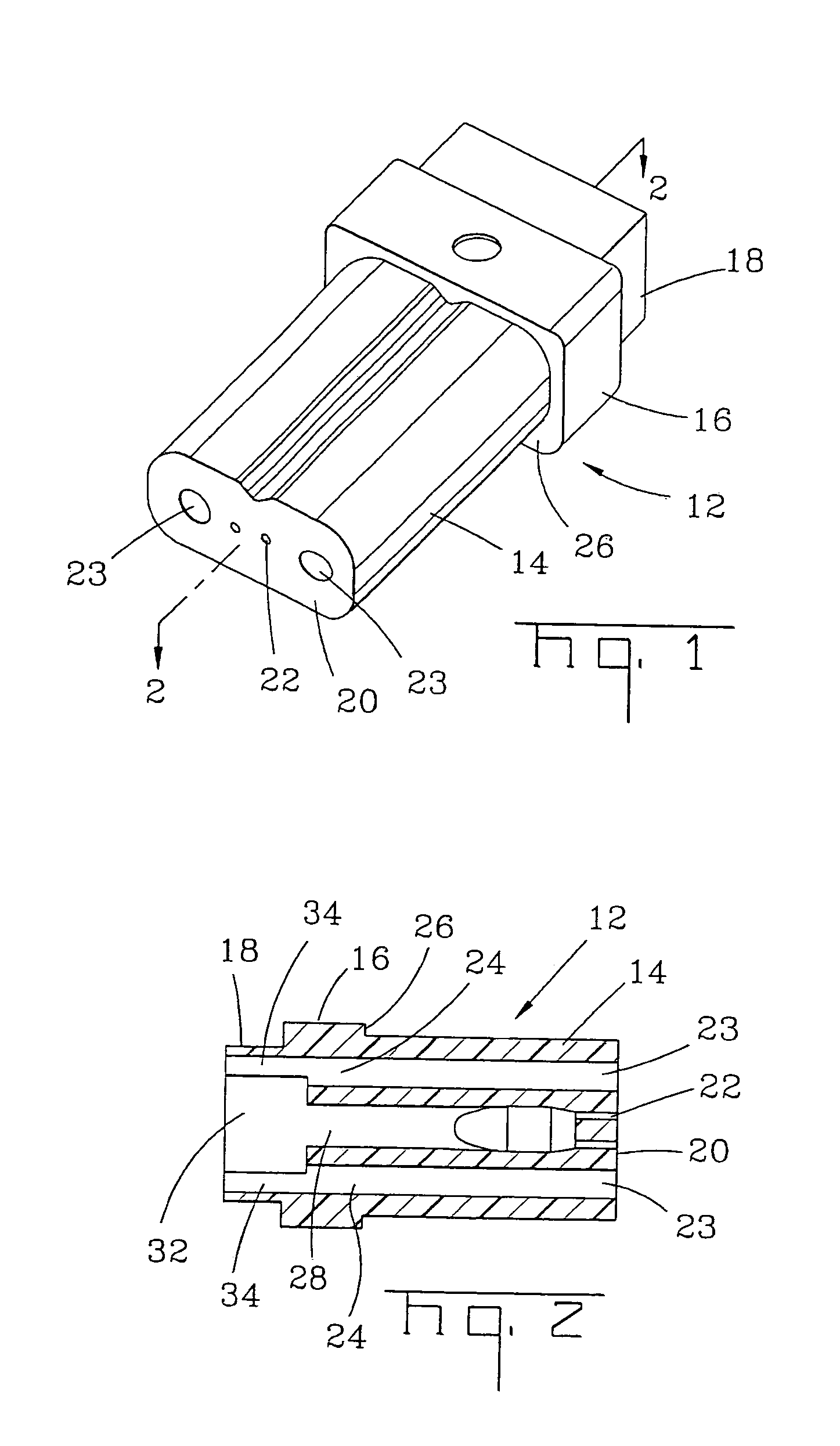
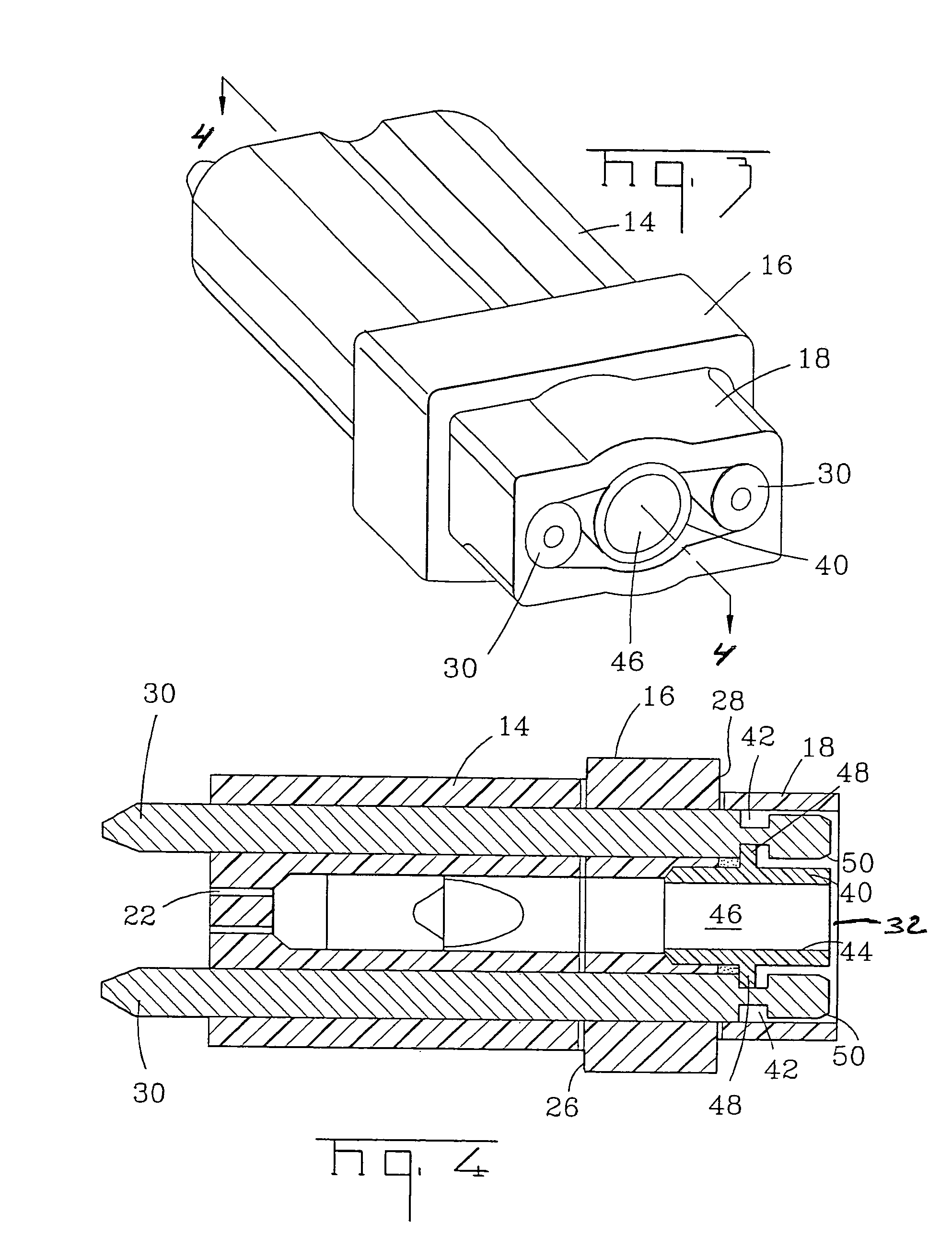
[0039]According to the present invention, a guide pin retainer for a fiber optic connector is provided that permits guide pins to be inserted into the connector after assembling the connector and polishing the front face of the ferrule without disassembling the connector. By way of example and not by way of limitation, various embodiments of such a guide pin retainer are shown and described. An associated method of efficiently fabricating the guide pin ret...


PUM


Abstract

A pin retainer for a fiber optic connector includes a ferrule having a front face defining a hole for receiving a guide pin. The pin retainer permits the guide pin to be inserted in the field following assembly of the connector and polishing the front face of the ferrule. The pin retainer includes a frame and at least one retaining tab for engaging the guide pin when the guide pin is inserted into the hole from the front face. The frame may have an open side for permitting the pin retainer to be fabricated using a highly efficient wire EDM process. The pin retainer provides a pin retention force of at least about 8 lbs and may include a plurality of retaining tabs for engaging the guide pin in more than one location. The ferrule may be provided with an external feature to position the pin retainer on the ferrule.

Description

CROSS REFERENCE TO RELATED APPLICATIONS[0001]This application is a continuation-in-part of U.S. patent application Ser. No. 09 / 878,566, filed Jun. 11, 2001 which issued as U.S. Pat. No. 6,669,377 on Dec. 30, 2003.FIELD OF THE INVENTION[0002]The present invention relates generally to a guide pin retainer for a fiber optic connector and an associated fabrication method. More particularly, the invention relates to a generally planar guide pin retainer for a fiber optic connector that permits the guide pins to be inserted into the connector after assembling the connector and polishing the front face of the ferrule without disassembling the connector, and an associated method of efficiently fabricating the guide pin retainer.BACKGROUND OF THE INVENTION[0003]Multi-fiber cables or ribbons are being increasingly employed in a wide variety of applications. As such, several standard multi-fiber connectors have been developed and are commonly utilized. Perhaps the most common multi-fiber conne...

Claims


Application Information

Patent Timeline
Patent Type & Authority Patents(United States)
IPC IPC(8): G02B6/36G02B6/38G02B6/40
CPCG02B6/3846G02B6/3885G02B6/3882G02B6/3865
Inventor LUTHER, JAMES P.DEJONG, MICHAELELKINS, II, ROBERT B.SZENTESI, OTTO I.THEUERKORN, THOMAS
Owner CORNING OPTICAL COMM LLC
Why Eureka
Try Eureka