Multi-interface and multi-bus structured solid-state storage subsystem

a solid-state storage and multi-bus technology, applied in the field of multi-bus structured solid-state storage subsystems, can solve the problems of inability to support a large percentage of systems in the field for which it is designed, the designer may be limited to using an on-board ide controller, and the subsystem relying entirely on either the ieee-1394 signal interface or the usb 2.0 signal interfa

Active Publication Date: 2010-03-23
WESTERN DIGITAL TECH INC
View PDF10 Cites 165 Cited by
  • Summary
  • Abstract
  • Description
  • Claims
  • Application Information

AI Technical Summary

Benefits of technology

[0008]Consequently, it would be advantageous to develop systems and methods to support multiple signal interfaces and bus structures within a single storage subsystem.
[0009]In certain embodiments disclosed herein, a solid-state storage subsystem may be connected to multiple host systems via multiple bus structures thereby reducing the number of different storage subsystems a manufacturer or designer needs to offer to meet the demands of various end customers.
[0012]The systems and methods disclosed herein advantageously describe a storage subsystem simultaneously connected across multiple host systems, using different signal interfaces and a priority management scheme for handling multiple data access commands. Advantageously, the consolidation of multiple host system data collection needs into a single storage subsystem reduces cost and board space. Yet another advantage disclosed herein is the capability of using multiple methods of interfacing with a storage subsystem for convenient storage or retrieval of data. For example, a storage subsystem may advantageously store data collected by a recording system via one signal interface and may upload data to a personal computer for analysis via another signal interface.
[0013]In certain embodiments, a host system may advantageously switch the signal interface and bus structure being used based on changing environmental conditions. If multiple bus structures are used to connect a single host system with a single storage subsystem, then such redundancy may be used to advantageously minimize potential loss of critical data. For example, if one bus structure connecting the host system and the storage subsystem were to cease operation, the host system may revert to another connection to resume data in order to transfer.

Problems solved by technology

Design constraints may typically include practical environmental and development matters: the distance separating the storage subsystem and a host system interfaced with the storage subsystem; power consumption; rates of data transfer; design time available on a project; and the cost to implement the bus structure for that signal interface.
If a Single Board Computer is used the designer may be limited to using an on-board IDE controller and PATA signal interface regardless of the application because of these time and budget considerations.
A storage subsystem relying entirely on either the IEEE-1394 signal interface or USB 2.0 signal interface will therefore not be compatible with a large percentage of systems in the field for which it is designed.
Other host computing systems operate multiple applications, and may face different constraints with each application.

Method used


Image

  • Multi-interface and multi-bus structured solid-state storage subsystem
  • Multi-interface and multi-bus structured solid-state storage subsystem
  • Multi-interface and multi-bus structured solid-state storage subsystem

Examples


Embodiment Construction

[0025]A solid-state storage subsystem, and associated processes that may be implemented by multiple host computing systems, will now be described with reference to the drawings. This description is intended to illustrate preferred embodiments of the invention, and not limit the invention. The invention is defined by the claims.

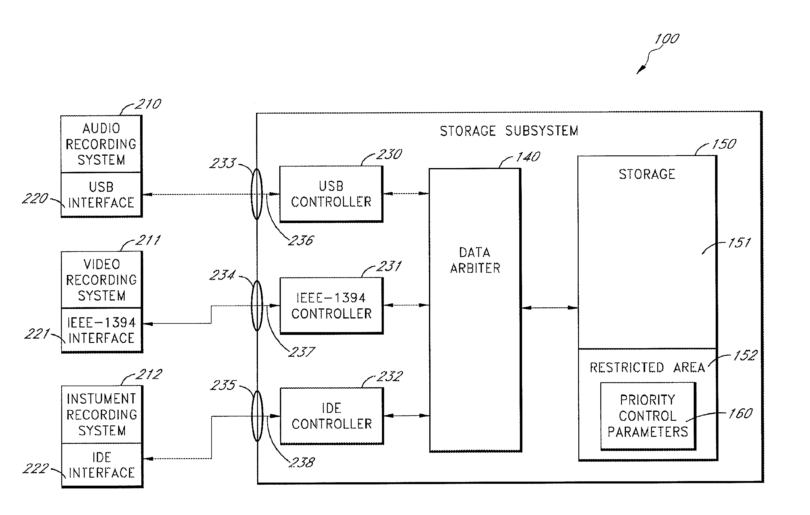
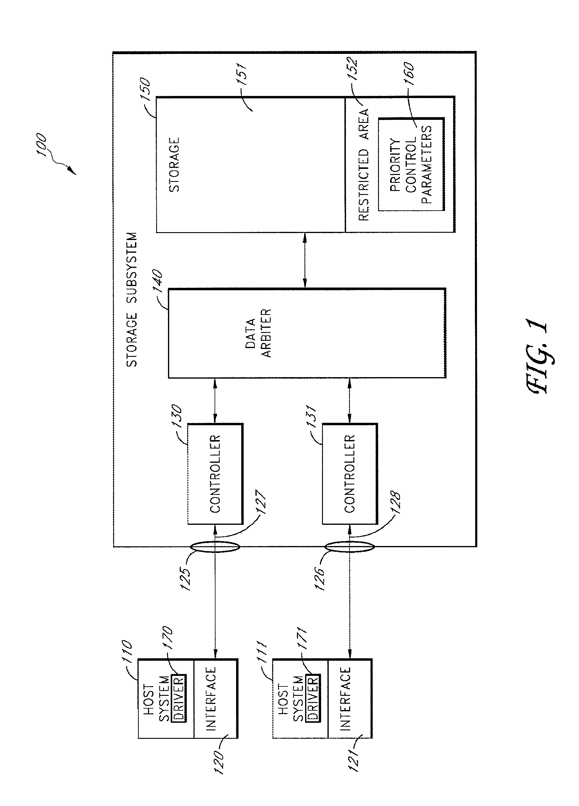
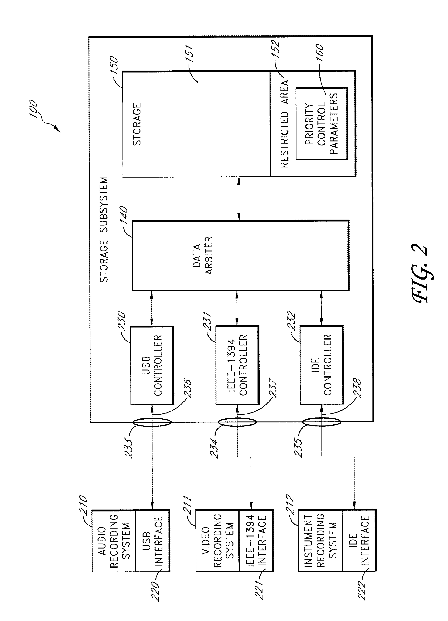
[0026]FIG. 1 is a block diagram illustrating multiple host systems 110 and 111 coupled to a solid-state storage subsystem 100 according to one embodiment. Although two host systems 110 and 111 are shown, any number of host systems may be coupled with storage subsystem 100 according to different embodiments. Each host system 110 and 111 may comprise a computer such as a personal computer, workstation, recording device, router, blade server or any other type of computing device. The host systems 110 and 111 store data on the storage subsystem 100. In some embodiments, operating system functionality and a boot process may be provided by the storage subsystem 100....


PUM


Abstract

A solid-state storage subsystem, such as a non-volatile memory card or drive, includes multiple interfaces and a memory area storing information used by a data arbiter to prioritize data commands received through the interfaces. As one example, the information may store a priority ranking of multiple host systems that are connected to the solid-state storage subsystem, such that the data arbiter may process concurrently received data transfer commands serially according to their priority ranking. A host software component may be configured to store and modify the priority control information in solid-state storage subsystem's memory area.

Description

BACKGROUND[0001]1. Technical Field[0002]The present invention relates to solid-state storage subsystems. More specifically, the present invention relates to multiple signal interfaces and bus structures for a single solid-state storage subsystem.[0003]2. Description of the Related Art[0004]Solid-state storage subsystems transfer data with host computer systems by means of a wide variety of signal interfaces. A signal interface is typically selected for a particular application based on design constraints facing that application. Design constraints may typically include practical environmental and development matters: the distance separating the storage subsystem and a host system interfaced with the storage subsystem; power consumption; rates of data transfer; design time available on a project; and the cost to implement the bus structure for that signal interface. Because constraints are often similar for similar applications, a particular signal interface may become standard for a...

Claims


Application Information

Patent Timeline
Patent Type & Authority Patents(United States)
IPC IPC(8): G06F13/36
CPCG06F3/0607G06F3/0659G06F3/0661G06F3/0679
Inventor DIGGS, MARK S.MERRY, JR., DAVID E.
Owner WESTERN DIGITAL TECH INC
Why Eureka
Try Eureka