Wind Turbine Generator, Active Damping Method Thereof, and Windmill Tower

a technology of active damping control and wind turbine generator, which is applied in the direction of mechanical power/torque control, ratio control, wind energy generation, etc., can solve the problems of increasing the weight of the nacelle, increasing the size of the nacelle, and increasing the cost, so as to reduce the vibration of the windmill tower, the cost of installing and operating the active damping control can be markedly reduced, and the cost of low cost

Inactive Publication Date: 2008-08-28
MITSUBISHI HEAVY IND LTD
View PDF73 Cites 79 Cited by
  • Summary
  • Abstract
  • Description
  • Claims
  • Application Information

AI Technical Summary

Benefits of technology

[0050]By applying the wind turbine generator of the present invention to a windmill tower, the cost of installing and operating the active damping control can be markedly reduced, and vibrations of the windmill tower can be reduced at low cost. Furthermore, unlike the known AMD method, since a heavy object (mass) and an actuator for the heavy object are not used, the weight of the nacelle does not increase and the strength of the windmill tower need not be increased. Thus, vibrations of the windmill tower can be redu

Problems solved by technology

Therefore, this method is no different from the known AMD method, resulting in an increase in the weight of the nacelle.
Furthermore, a

Method used


Image

  • Wind Turbine Generator, Active Damping Method Thereof, and Windmill Tower
  • Wind Turbine Generator, Active Damping Method Thereof, and Windmill Tower
  • Wind Turbine Generator, Active Damping Method Thereof, and Windmill Tower

Examples


Embodiment Construction

[0063]Embodiments of a wind turbine generator, an active damping method thereof, and a windmill tower of the present invention will now be described in detail with reference to the attached drawings.

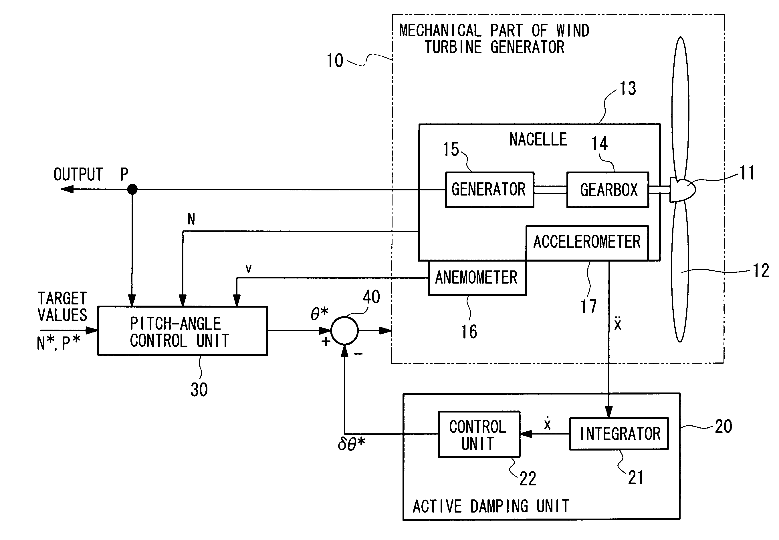
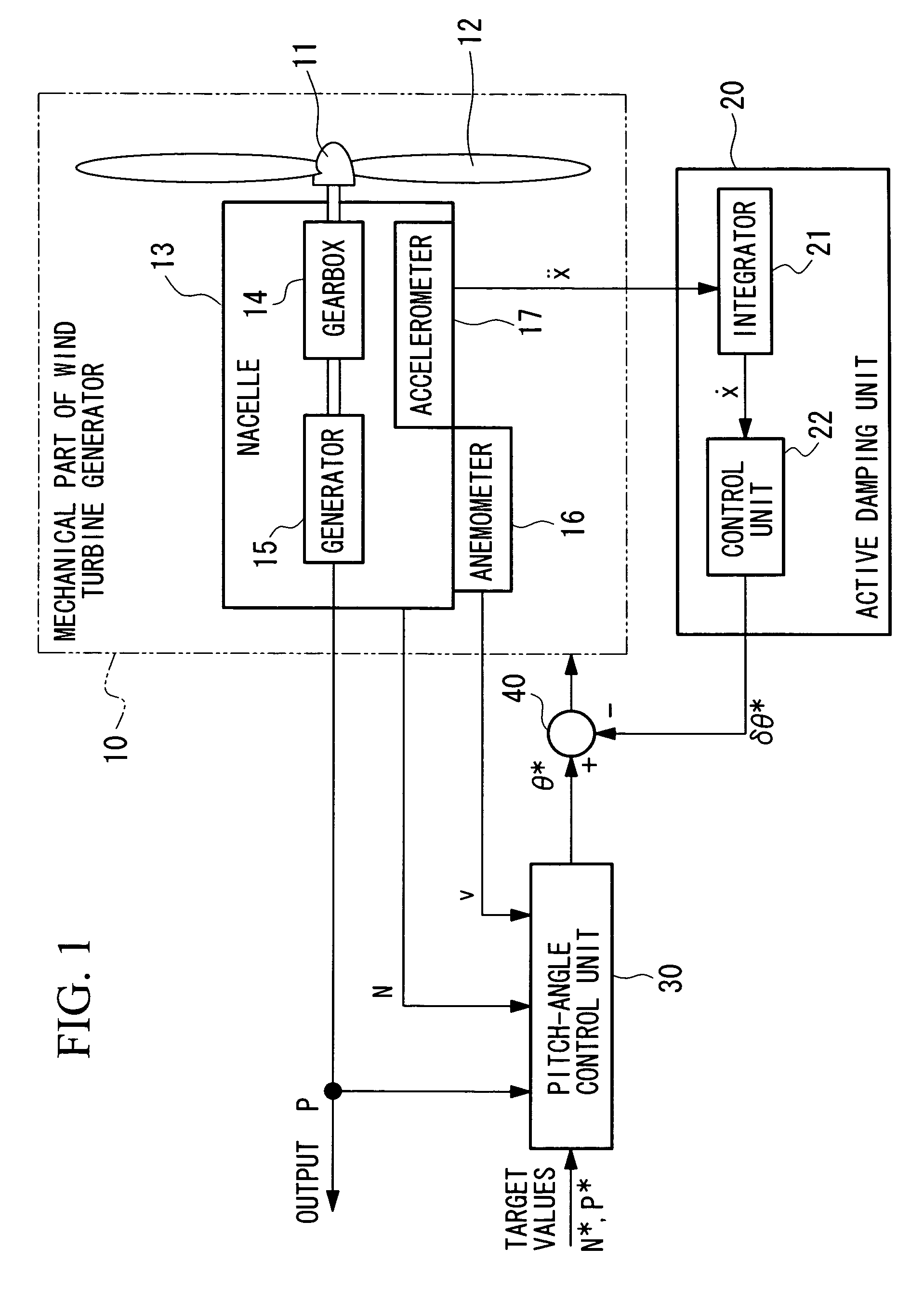
[0064]FIG. 1 is a diagram showing the configuration of a wind turbine generator according to an embodiment of the present invention. In the figure, the wind turbine generator of this embodiment includes a mechanical part 10 of the wind turbine generator, an active damping unit 20, a pitch-angle control unit 30, and a subtracter 40. First, the outline of the components in the wind turbine generator of this embodiment will be described.

[0065]The mechanical part 10 of the wind turbine generator includes a windmill rotor 11, windmill blades 12, a nacelle 13, and an anemometer 16 as main components. The nacelle 13 includes a gearbox 14, a generator 15, and an accelerometer 17.

[0066]In the mechanical part 10 of the wind turbine generator, a plurality of windmill blades 12 attached to the windm...


PUM


Abstract

A wind turbine generator, an active damping method thereof, and a windmill tower in which vibrations of the wind turbine generator itself or the windmill tower can be reduced at low cost are provided. The acceleration due to vibrations of a nacelle (13) is detected with an accelerometer (17) attached to the nacelle (13). In an active damping unit (20), a pitch angle of windmill blades (12) for generating a thrust on the windmill blades (12) so as to cancel out the vibrations of the nacelle (13) is calculated on the basis of the acceleration, and the pitch angle is output as a blade-pitch-angle command δθ* for damping. On the other hand, in a pitch-angle control unit (30), a pitch angle of the windmill blades (12) for controlling the output to be a predetermined value is calculated, and the pitch angle is output as a blade-pitch-angle command θ* for output control. The blade-pitch-angle command δθ* for damping is combined with the blade-pitch-angle command θ* for output control using a subtracter (40). The pitch angle of the windmill blades is controlled on the basis of the resulting blade-pitch-angle command after combining.

Description

TECHNICAL FIELD[0001]The present invention relates to wind turbine generators, active damping methods thereof, and windmill towers in which vibrations induced by fluctuations of wind speed can be suppressed. In particular, the present invention relates to wind turbine generators, active damping methods thereof, and windmill towers in which vibrations of the wind turbine generators themselves or the windmill towers can be reduced at low cost and without increasing the weight of a nacelle.BACKGROUND ART[0002]Wind turbine generators generally have a structure in which heavy objects such as blades, a gearbox, and a generator are provided at the top of a cylindrical tower having a height of several tens of meters; therefore, vibrations induced by fluctuations of wind speed are extremely large. Such vibrations increase the fatigue loading of structural components, resulting in a decrease in the life of the windmill tower.[0003]Recently, the size of wind turbine generators has been increas...

Claims


Application Information

Patent Timeline
IPC IPC(8): F03D7/04F01D7/02G05D15/00
CPCF03D7/0224F03D9/002F03D7/043F05B2260/71F05B2260/74F05B2260/821F05B2260/96F05B2270/1021F05B2270/309F05B2270/334F05B2270/404F05B2270/807Y02B10/30Y02E10/723F03D7/0296F03D9/25Y02E10/72F03D7/04
Inventor WAKASA, TSUYOSHIIDE, KAZUNARIHAYASHI, YOSHIYUKISHIBATA, MASAAKI
Owner MITSUBISHI HEAVY IND LTD
Why Eureka
Try Eureka