Zoom lens system

a zoom lens and zoom technology, applied in the field of zoom lens systems, can solve the problems of reducing the correction performance of chromatic aberration, increasing spherical aberration, and not being favorable to chromatic aberration, so as to suppress the production of improve the correction performance of the second lens group for various types of aberration.

Inactive Publication Date: 2009-04-16
NITTO OPTICAL CO LTD
View PDF1 Cites 13 Cited by
  • Summary
  • Abstract
  • Description
  • Claims
  • Application Information

AI Technical Summary

Benefits of technology

[0011]In this zoom lens system, at least one aspherical surface is provided in the first lens group and at least two aspherical surfaces are provided in the second lens group. By doing so, in particular the correction performance of the second lens group for various types of aberration is improved. Accordingly, it is possible to suppress the production of various types of aberration in the respective lens groups and to favorably correct such aberration even if the refractive powers of the respective lens groups are suppressed. This means that it is possible to make the refractive power of the third lens group comparatively low and to suppress the change in the angle of incidence of the light rays on the image pickup surface when zooming from the wide angle end to the telephoto end. Accordingly, it is possible to suppress the drop in the amount of light at the image pickup device (image pickup element) disposed at the image-forming plane on the image-forming side of the lens system. Condition (3) sets the power distributed to the third lens group. The upper limit in Condition (3) is effective in suppressing a drop in

Problems solved by technology

However, in the cemented lens, increasing of the spherical aberration and redu

Method used


Image

  • Zoom lens system
  • Zoom lens system
  • Zoom lens system

Examples


Embodiment Construction

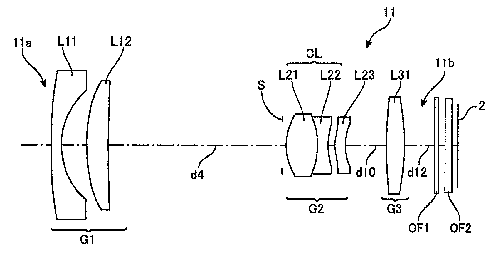
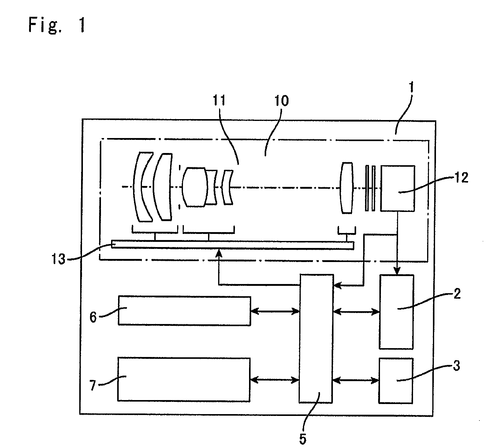
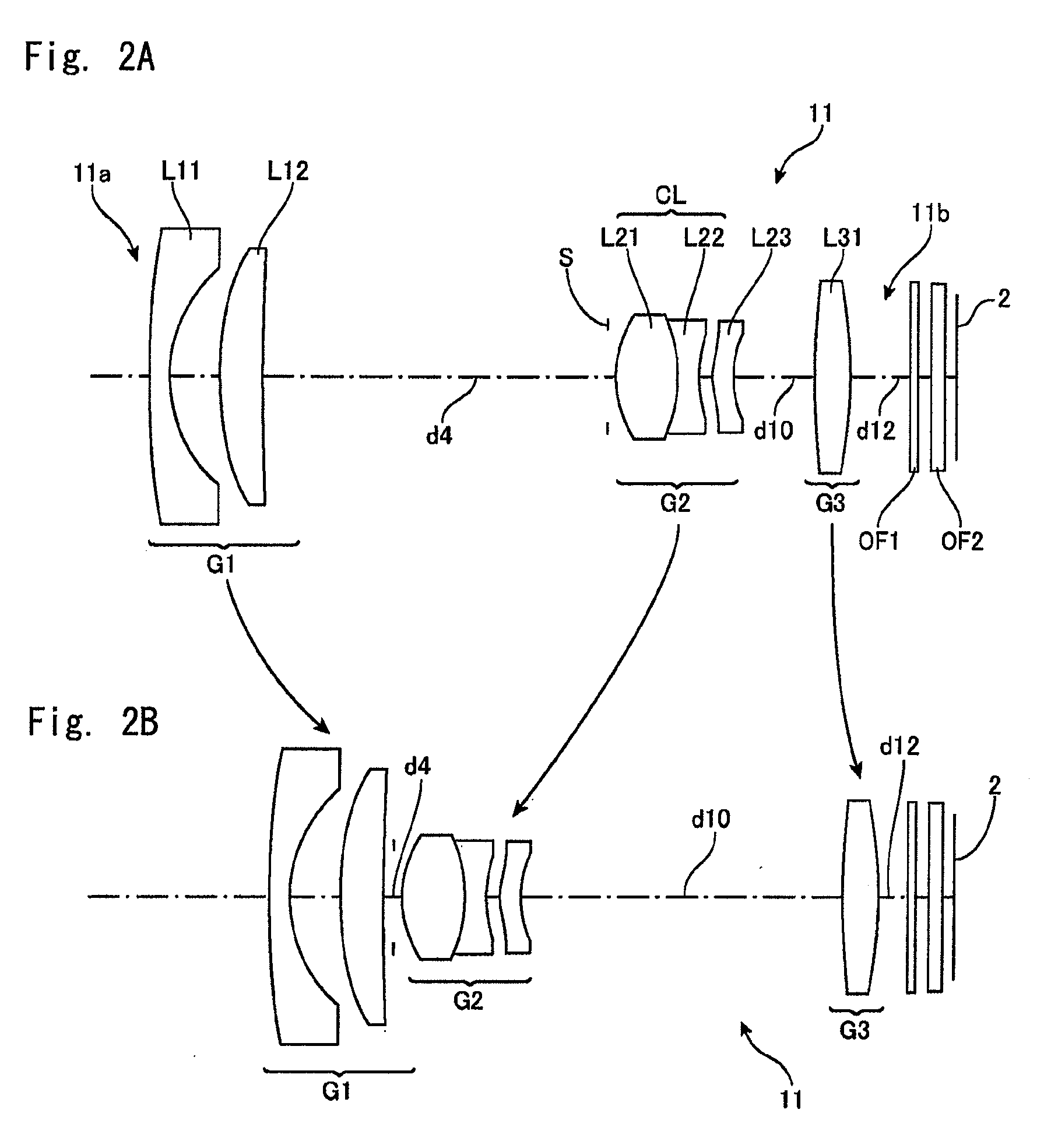
[0025]FIG. 1 shows the overall arrangement of an information terminal equipped with a camera function. In more detail, this information terminal 1 is a mobile phone equipped with a camera function or a PDA (Personal Data Acquisition, Personal Digital Assistance) equipped with a camera function. The information terminal 1 is equipped with a digital camera function 10 which includes a zoom lens system 11, an image pickup device 12 disposed at an image formation position (an image focus plane) of the zoom lens system 11, and a lens driving mechanism 13 that carries out a zooming operation by moving lens groups in the zoom lens system 11. The information terminal 1 further includes a display device 2, a data input / output device 3, a control unit 5 with functions such as a CPU, a memory device 6 such as a RAM disk and / or a hard disk, and a communication unit 7 for wirelessly connecting to a public telephone network and / or a computer network. The image pickup device 12 is a CCD or CMOS se...


PUM


Abstract

A zoom lens system consists, in order from an object side to an image-forming side, of a first negative lens group G1, a second positive lens group G2, and a third positive lens group G3. The first lens group G1 consists of one negative lens and one positive lens, the second lens group G2 consists of a cemented lens composed of a positive lens and a negative lens, and one meniscus lens that is concave on the image-forming side, the third lens group G3 consists of a single positive lens, and a combined focal length f2 of the second lens group, a focal length Lf23 of the meniscus lens of the second lens group, a combined focal length fw of the zoom lens system at a wide angle end, a combined focal length f3 of the third lens group, a radius of curvature Ro of an object side surface of the positive lens in the cemented lens, and a radius of curvature Ri of an image-forming side surface of the positive lens in the cemented lens satisfy the following conditions.
0<|f2/Lf23|<0.3
−2.0<Ri/Ro<−1.0
0.25<fw/f3<0.45

Description

CROSS-REFERENCE TO RELATED APPLICATIONS[0001]This application is based upon and claims the benefit of priority from the prior Japanese Patent Application No. 2007-266708, filed Oct. 12, 2007, the entire contents of which are incorporated herein by reference.BACKGROUND[0002]The present invention relates to a zoom lens system that is suited to mounting in a digital camera or an information terminal such as a mobile phone that is equipped with a digital camera function.[0003]A digital camera that uses an image pickup device such as a CCD or a CMOS to obtain an image formed by a lens as digital data is known. An information terminal such as a mobile telephone, a cellular phone etc., in which a digital camera is incorporated is also known.[0004]Japanese Laid-Open Patent Publication No. 2001-296476 discloses a zoom lens composed of three lens groups with negative, positive and positive refractive powers in that order from the object side, where the first group consists of two lenses, the ...

Claims


Application Information

Patent Timeline
IPC IPC(8): G02B15/177
CPCG02B15/177G02B15/143507
Inventor IIJIMA, KENJI
Owner NITTO OPTICAL CO LTD
Why Eureka
Try Eureka