Imaging optical system

a technology of optical system and image, applied in the field can solve the problems of difficult miniaturization (slimming down) of imaging optical system, large momentum of camera, and correction of abaxial aberration such as coma, etc., and achieve the effect of favorable correction of abaxial aberration

Inactive Publication Date: 2016-05-05
HOYA CORP
View PDF3 Cites 79 Cited by
  • Summary
  • Abstract
  • Description
  • Claims
  • Application Information

AI Technical Summary

Benefits of technology

[0011]The present invention has been devised in view of the above-mentioned problems, and provides an imaging optical system having an f-number of approximately 2.0 which enables a large amoun

Problems solved by technology

However, since the imaging optical system in each of Patent Literature Nos. 1 through 4 has an inappropriate lens profile or refractive power in the positive lens element provided closest to the object side (and also an inappropriate refractive power balance between this positive lens element and the other lens elements), miniaturization (slimming down) o

Method used


Image

  • Imaging optical system
  • Imaging optical system
  • Imaging optical system

Examples


numerical embodiment 1

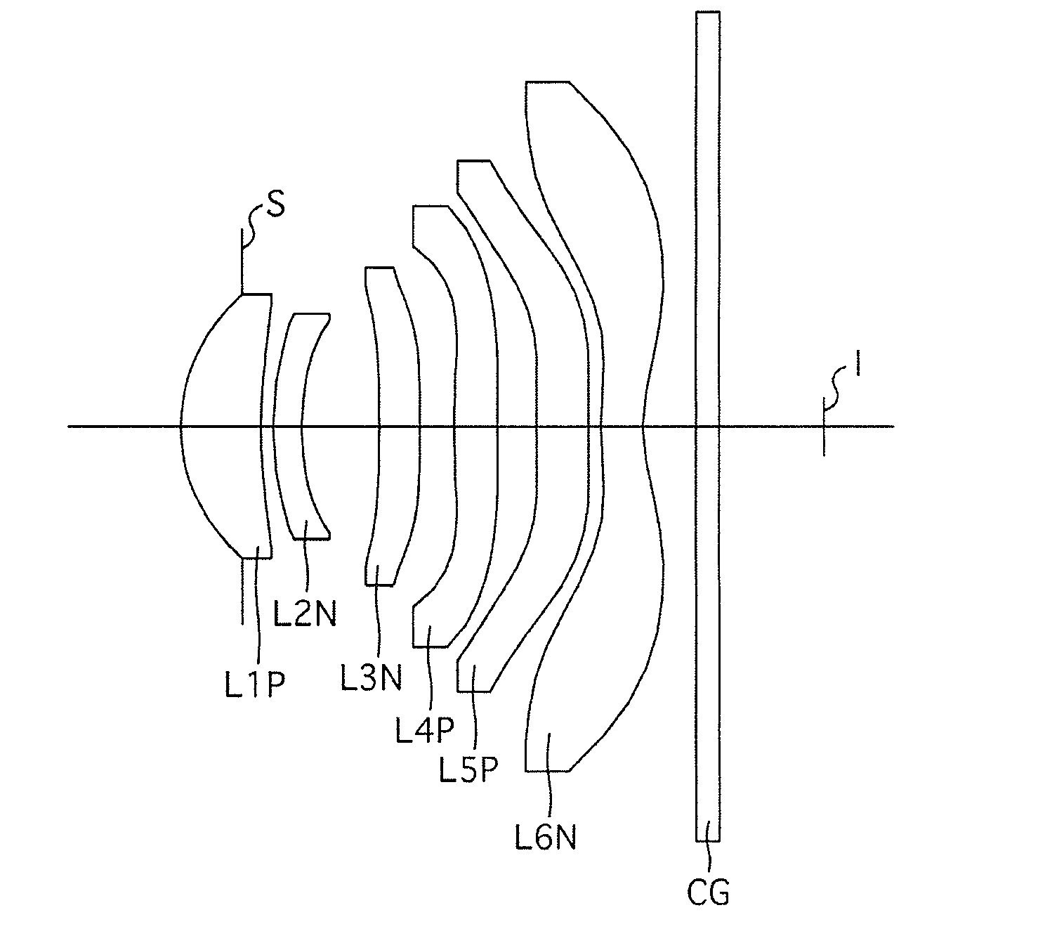
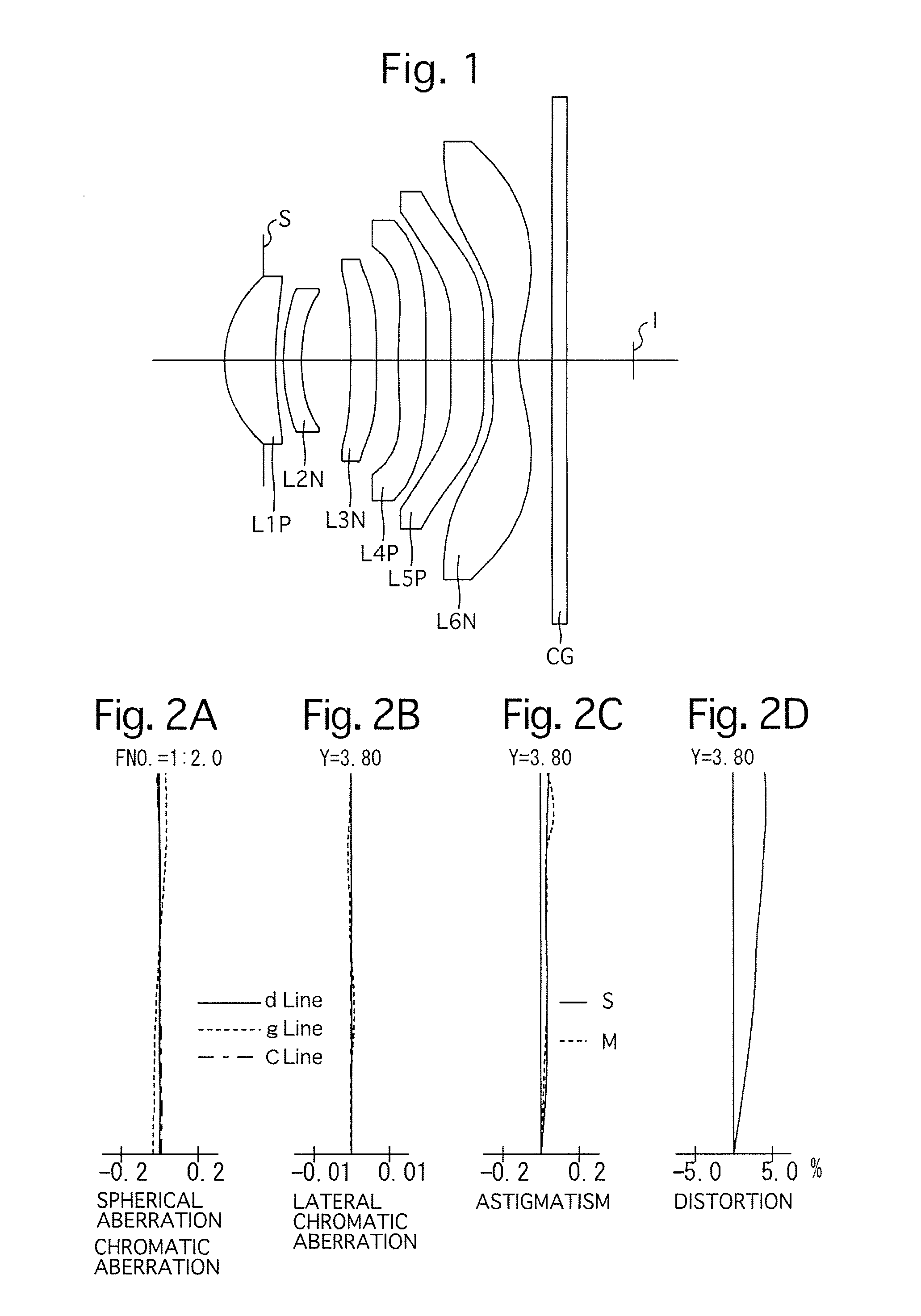
[0082]FIGS. 1 through 2D and Tables 1 through 3 show a first numerical embodiment of the imaging optical system. FIG. 1 shows a lens arrangement of the first numerical embodiment of the imaging optical system. FIGS. 2A, 2B, 2C and 2D show various aberrations that occurred in the lens arrangement shown in FIG. 1. Table 1 shows the lens surface data, Table 2 shows various data of the imaging optical system, and Table 3 shows aspherical surface data.

[0083]The imaging optical system of the first numerical embodiment is configured of a positive first lens element L1P having a convex surface on the object side (a positive meniscus lens element having a convex surface on the object side), a negative second lens element L2N having a concave surface on the image side (negative meniscus lens element having a convex surface on the object side), a negative third lens element L3N, a positive fourth lens element L4P, a positive fifth lens element L5P and a negative sixth lens element L6N, in that...

numerical embodiment 2

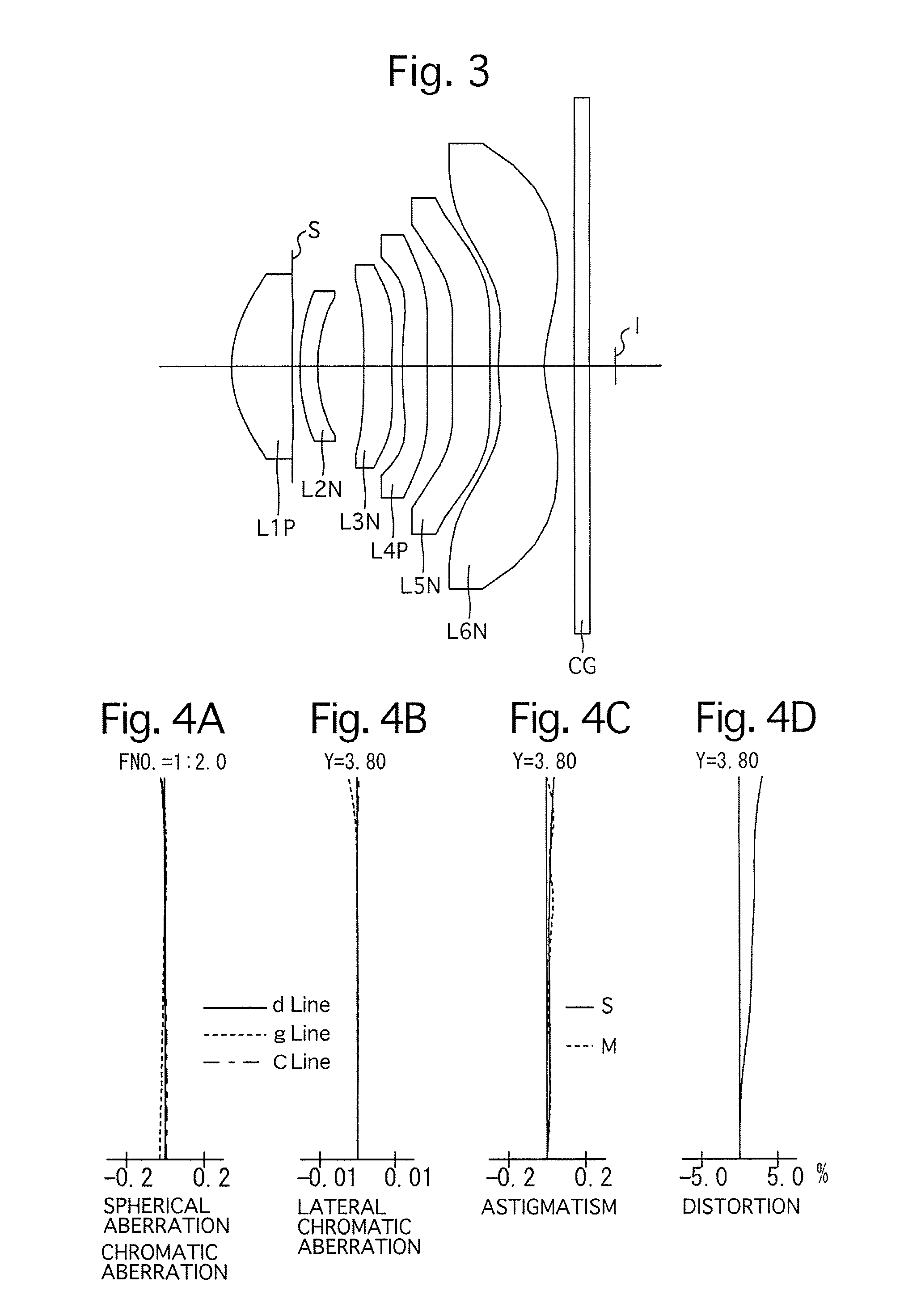
[0084]FIGS. 3 through 4D and Tables 4 through 6 show a second numerical embodiment of the imaging optical system. FIG. 3 shows a lens arrangement of the second numerical embodiment of the imaging optical system. FIGS. 4A, 4B, 4C and 4D show various aberrations that occurred in the lens arrangement shown in FIG. 3. Table 4 shows the lens surface data, Table 5 shows various data of the imaging optical system, and Table 6 shows aspherical surface data.

[0085]The fundamental lens arrangement of the second numerical embodiment is the same as that of the first numerical embodiment except for the following features:

[0086](1) The positive fifth lens element L5P is replaced with a negative fifth lens element L5N.

[0087](2) The diaphragm S is provided on a plane that is orthogonal to the optical axis and contacts the surface of the first lens element L1P on the image side.

TABLE 4LENS SURFACE DATASurf. No.RDN(d)ν(d)11.7830.841.4971081.6210.2420.00(Diaphragm)∞0.1132.8170.252.0017819.342.2850.665−...

numerical embodiment 3

[0088]FIGS. 5 through 6D and Tables 7 through 9 show a third numerical embodiment of the imaging optical system. FIG. 5 shows a lens arrangement of the third numerical embodiment of the imaging optical system. FIGS. 6A, 6B, 6C and 6D show various aberrations that occurred in the lens arrangement shown in FIG. 5. Table 7 shows the lens surface data, Table 8 shows various data of the imaging optical system, and Table 9 shows aspherical surface data.

[0089]The fundamental lens arrangement of the third numerical embodiment is the same as that of the first numerical embodiment.

TABLE 7LENS SURFACE DATASurf. No.RDN(d)ν(d)(Diaphragm)∞−0.4411.4430.631.4971081.625.4690.1533.5500.222.0017819.342.7700.565−9.0910.421.5435855.76−13.4550.24711.8740.451.5435855.7875.7640.35945.9520.471.6354823.91073.2870.10112.6020.521.5435855.7121.4260.4413∞0.211.5168064.214∞0.34

TABLE 8IMAGING OPTICAL SYSTEM DATAFocal length of imaging optical system [mm]:4.60f-number2.2Half angle of view [deg]:38.2Maximum image he...


PUM


Abstract

An imaging optical system includes a positive first lens element having a convex surface on the object side, a negative second lens element having a concave surface on the image side, a third lens element, a positive fourth lens element, a fifth lens element, and a negative sixth lens element provided with at least one aspherical surface that has inflection points other than at an optical axis thereof. The following conditions (1) and (2) are satisfied:
0.86<f/f12<1.20  (1), and
−0.71<(r11−r12)/(r11+r12)<−0.20  (2),
wherein f designates the focal length of the imaging optical system, f12 designates the combined focal length of the first and second lens elements, and r11 and r12 designate the radius of curvatures of surfaces on the object side and image side of the first lens element, respectively.

Description

BACKGROUND OF THE INVENTION[0001]1. Field of the Invention[0002]The present invention relates to an imaging optical system, e.g., an imaging optical system that is installed in a mobile device (a smart phone, etc.) having a built-in camera.[0003]2. Description of Related Art[0004]Patent Literature Nos. 1 through 4 each disclose an imaging optical system installed in, e.g., a mobile device, having a built-in camera, which provides an f-number of approximately 2.0 through 2.4 and a half angle-of-view of 35 degrees.[0005]The imaging optical system in each of Patent Literature Nos. 1 through 4 has a configuration of six lens elements, in which a positive lens element is provided closest to the object side, and a positive lens element or a negative lens element that has an aspherical surface having inflection points other than at the optical axis (at positions other than at an intersection point of the optical axis) is provided closest to the image side.[0006]Patent Literature 1: Japanes...

Claims


Application Information

Patent Timeline
IPC IPC(8): G02B13/00G02B27/00G02B9/62
CPCG02B13/0045G02B27/0025G02B9/62
Inventor KOREEDA, DAISUKE
Owner HOYA CORP
Why Eureka
Try Eureka