Optical system

Active Publication Date: 2007-01-18
CANON KK
View PDF7 Cites 14 Cited by
  • Summary
  • Abstract
  • Description
  • Claims
  • Application Information

AI Technical Summary

Benefits of technology

[0013] At least one exemplary embodiment is directed to an optical system for facilitating

Problems solved by technology

In correcting and/or reducing aberration of a lens, the retro focus lenses have a disadvantage in that negative distortion (barrel distortion) tends to occur, since a lens component with negative refractive power is disposed in the front and the refractive power is not symmetrical.
However, in general, since materials of a high index of refraction are of high dispersion, negative chromatic aberration of magnification (transverse chromatic aberration) tends to occur.
If the total optical length is reduced, a large amount of chromatic aberration appears.
Accordingly, it can

Method used


Image

  • Optical system
  • Optical system
  • Optical system

Examples


exemplary embodiment 1

[0133] A material that satisfies conditional expressions (1) and (2) and that is applied to a particular optical system is now herein described. In the following exemplary embodiments, a UV curable resin or a TiO2 particle dispersion material in which TiO2 particle are dispersed in the UV curable resin serving as a host polymer is employed as a material that satisfies conditional expressions (1) and (2).

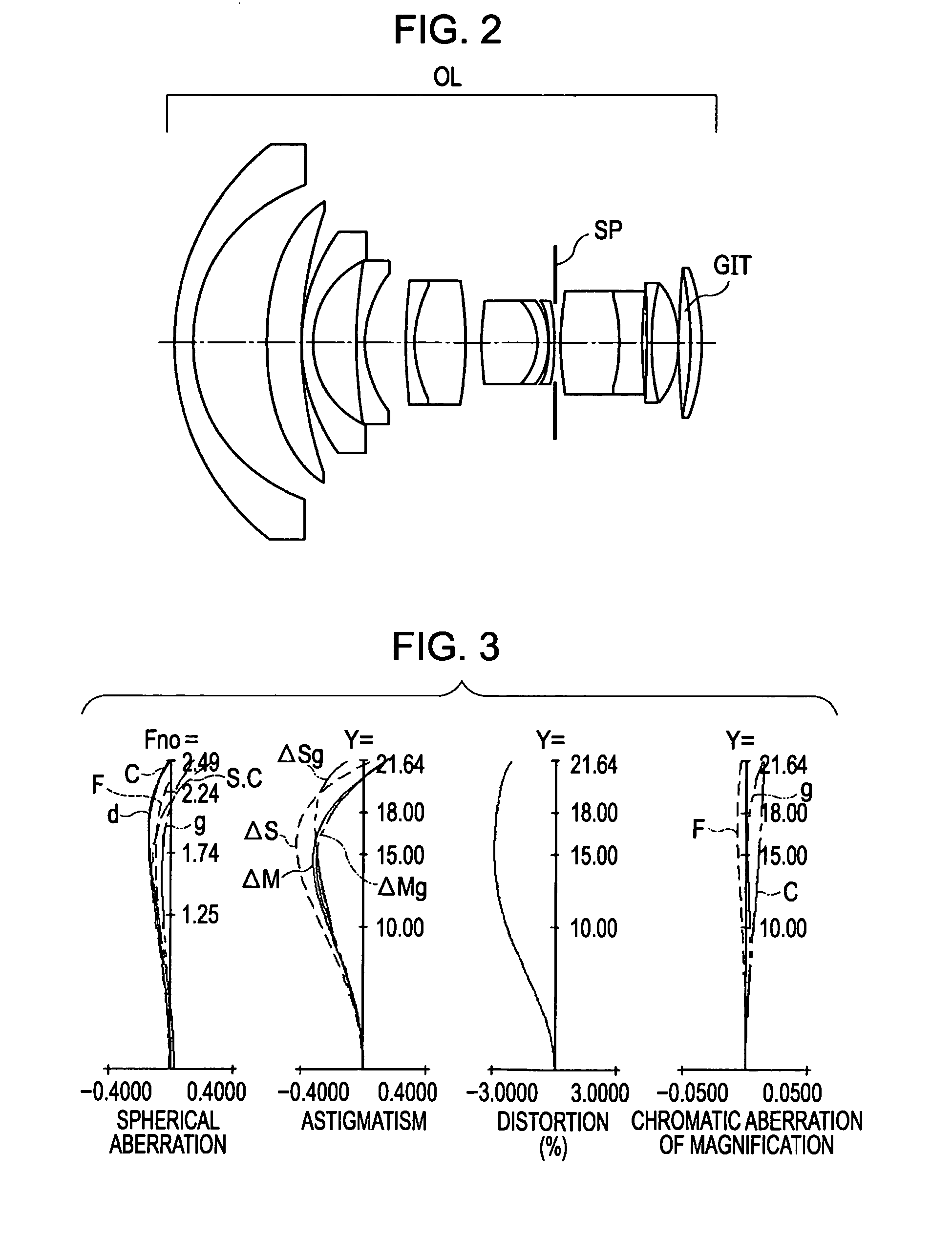
[0134]FIG. 2 is a sectional view of an optical system OL according to exemplary embodiment 1. In exemplary embodiment 1, a wide-angle lens (retro focus lens system), which can have a focal length of 14 mm, includes a refractive optical element formed from a mixture of TiO2 particles dispersed in a UV curable resin. In FIG. 2, a lens (layer) formed from the mixture is designated as GIT. An aperture stop is designated as SP. In FIG. 2, an object lies at the left of the optical system (front side) and an image is present at the right of the optical system (rear side). This is the same ...

exemplary embodiment 2

[0137]FIG. 4 is a sectional view of an optical system OLa according to exemplary embodiment 2. In exemplary embodiment 2, a wide-angle lens, which can have a focal length of 14 mm, includes a refractive optical element (e.g., formed from a mixture of TiO2 particles dispersed in a UV curable resin). In addition, the surface of the refractive optical element can be aspherized. In FIG. 4, a lens (layer) formed from a TiO2 particle dispersion material is designated as GIT. An aperture stop is designated as SP. FIG. 5 illustrates aberration graphs of the optical system according to exemplary embodiment 2 when focusing on an object at infinity.

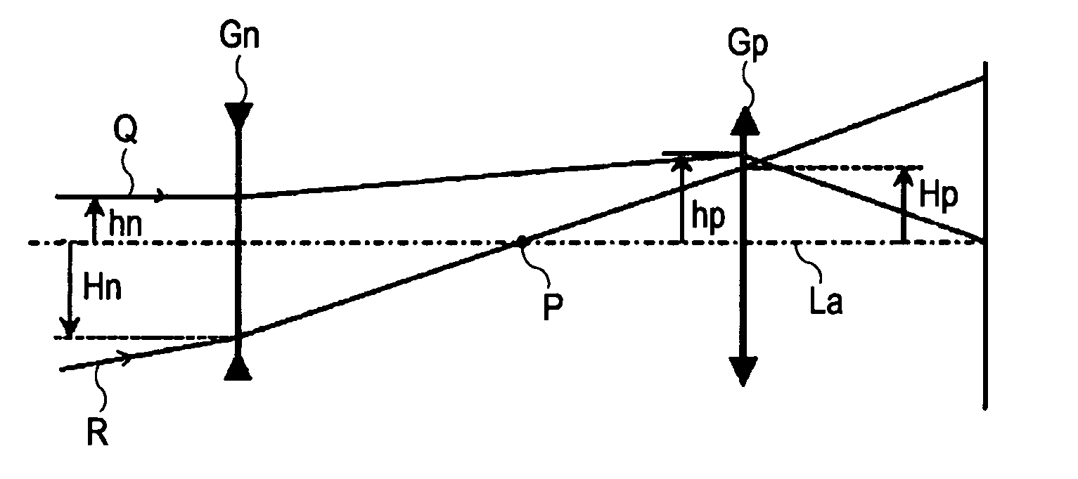
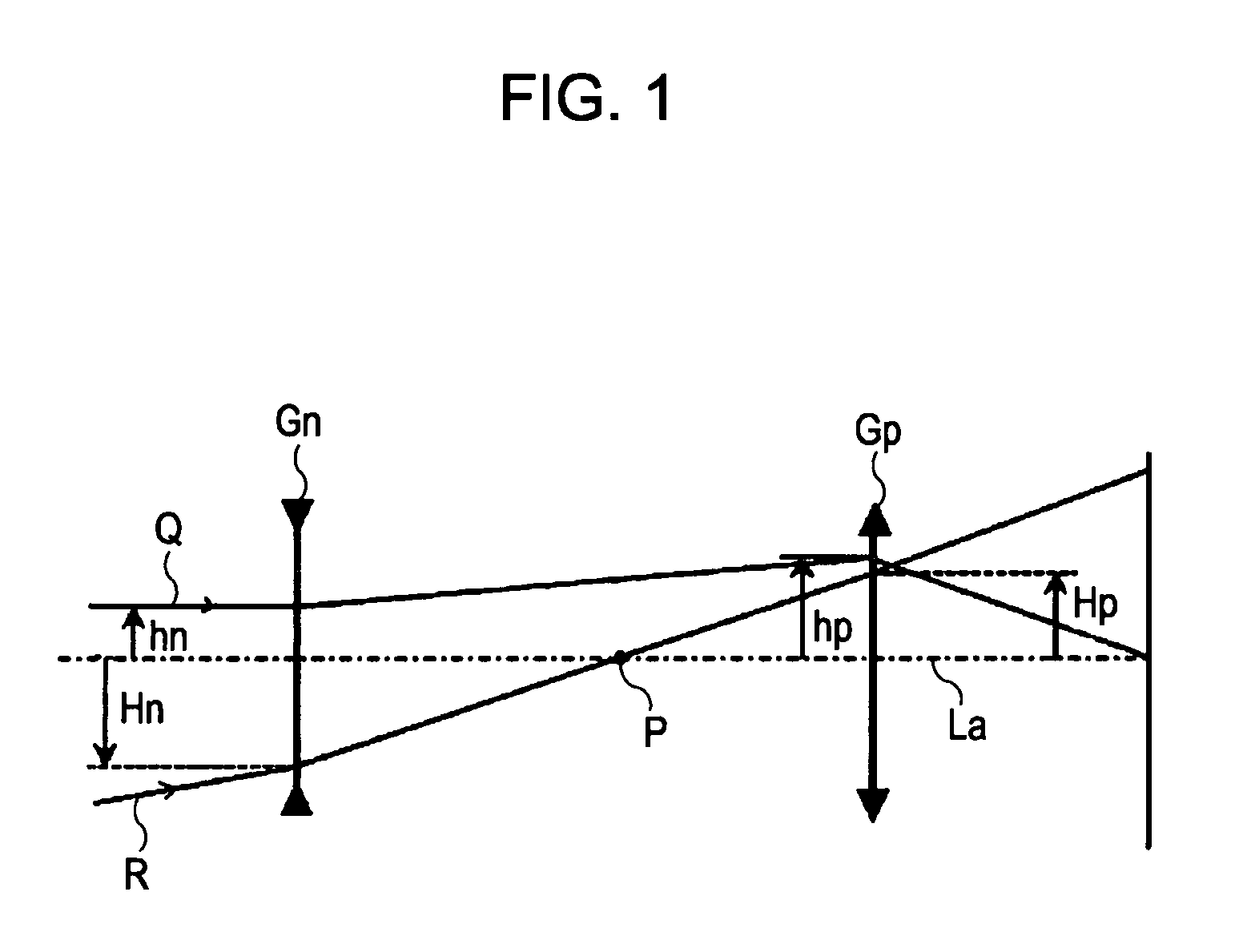
[0138] In the optical system according to exemplary embodiment 2, a lens GITa is introduced at the rear side where the passing position of a paraxial chief ray R (FIG. 1) is equivalently high from the optical axis La. At that time, the lens GIT has a shape so that a positive refractive power increases towards the periphery from the optical axis. Th...

exemplary embodiment 3

[0139]FIG. 6 is a sectional view of an optical system OLb according to exemplary embodiment 3. In exemplary embodiment 3, a wide-angle lens, which can have a focal length of 14 mm, includes a refractive optical element formed from a UV curable resin. In addition, the surface of the refractive optical element can be aspherized. In FIG. 6, a lens (layer) formed from the UV curable resin is designated as GITb. An aperture stop is designated as SP. FIG. 7 illustrates aberration graphs of the optical system according to exemplary embodiment 3 when focusing on an object at infinity.

[0140] In the optical system according to exemplary embodiment 3, a lens GITb is introduced at the front side where the passing position of a paraxial chief ray R (FIG. 1) is equivalently low from the optical axis La. At that time, the lens GITb has a shape so that a negative refractive power increases towards the periphery from the optical axis. Thus, the negative refractive power is provided to the lens GITb...


PUM


Abstract

At least one exemplary embodiment is directed to A retro focus optical system that is capable of sufficiently correcting and/or reducing various aberrations including the chromatic aberration. The optical system includes a refractive optical element including a solid material. The Abbe number νd and the partial dispersion ratio θgF of the solid material along with a shape of the refractive optical element can reduce various aberrations.

Description

BACKGROUND OF THE INVENTION [0001] 1. Field of the Invention [0002] The present invention relates to an optical system and, in particular though not exclusively, to an optical system that can be used for photographing optical systems, observation optical systems, projection optical systems, and readout optical systems. [0003] 2. Description of the Related Art [0004] Retro focus lens systems (negative lead type) have been widely used to provide a wide angle (wide viewing angle) to lens systems. Such a retro focus lens system includes a lens component with negative refractive power disposed in the front and a lens component with positive refractive power disposed in the rear, thereby providing a short focal length and a long back focus. As used herein, the term “front” refers to a side adjacent to a subject in photographing optical systems (e.g., cameras) and a side adjacent to a screen in projection optical systems (e.g., projectors). The term “rear” refers to a side adjacent to an i...

Claims


Application Information

Patent Timeline
IPC IPC(8): G02B3/00G02B25/00G02B13/00G02B7/00G02B11/00G02B15/00G02B17/00G02B9/00
CPCG02B13/0095G02B27/0062G02B27/0025
Inventor YOKOYAMA, TAKAYOSHI
Owner CANON KK
Why Eureka
Try Eureka