Projection lens and projection type display device using the same

a projection lens and projection type technology, applied in the field of projection lenses, can solve the problems of increasing the spatial size of the device, the inability to realize compactification of the device size, and the length of the lens along the optical axis, and achieve the effect of wide viewing angle and good aberration correction function

Active Publication Date: 2009-04-30
FUJI PHOTO OPTICAL CO LTD
View PDF4 Cites 14 Cited by
  • Summary
  • Abstract
  • Description
  • Claims
  • Application Information

AI Technical Summary

Benefits of technology

[0028]Since the projection lens of the invention has the above constitution, the reduction side is made telecentric, and a good aberration correcting function can be realized.
[0029]Further, since the above conditional expression (1) is satisfied, the back focal length suitable to recent projection lenses can be secured. Further, since the above conditional expression (2) is satisfied, it is possible to attain compactification of the entire lens system while realizing a wider viewing angle Further, the projection type display device of the invention, since uses the projection lens of the invention, can be provided as a high-resolution display device which corrects satisfactorily various aberrations and can attain the compactification.

Problems solved by technology

However, in such the projection lens in the rear type device, in order to reduce the thickness of the cabinet, a prism or a mirror for turning back an optical axis is arranged in a lens system, and a full lens length along the optical axis becomes long, so that increase in spatial size of the device is caused.
Accordingly, in case that the projection lenses described in the above Patent Documents are used in the front type projection type display device, there is a problem that compactification of the device size cannot be realized.
Further, the front type projection type display system (including the display device and the screen), compared with the rear type, has limits in size of installation space of the system.

Method used


Image

  • Projection lens and projection type display device using the same
  • Projection lens and projection type display device using the same
  • Projection lens and projection type display device using the same

Examples


example 1

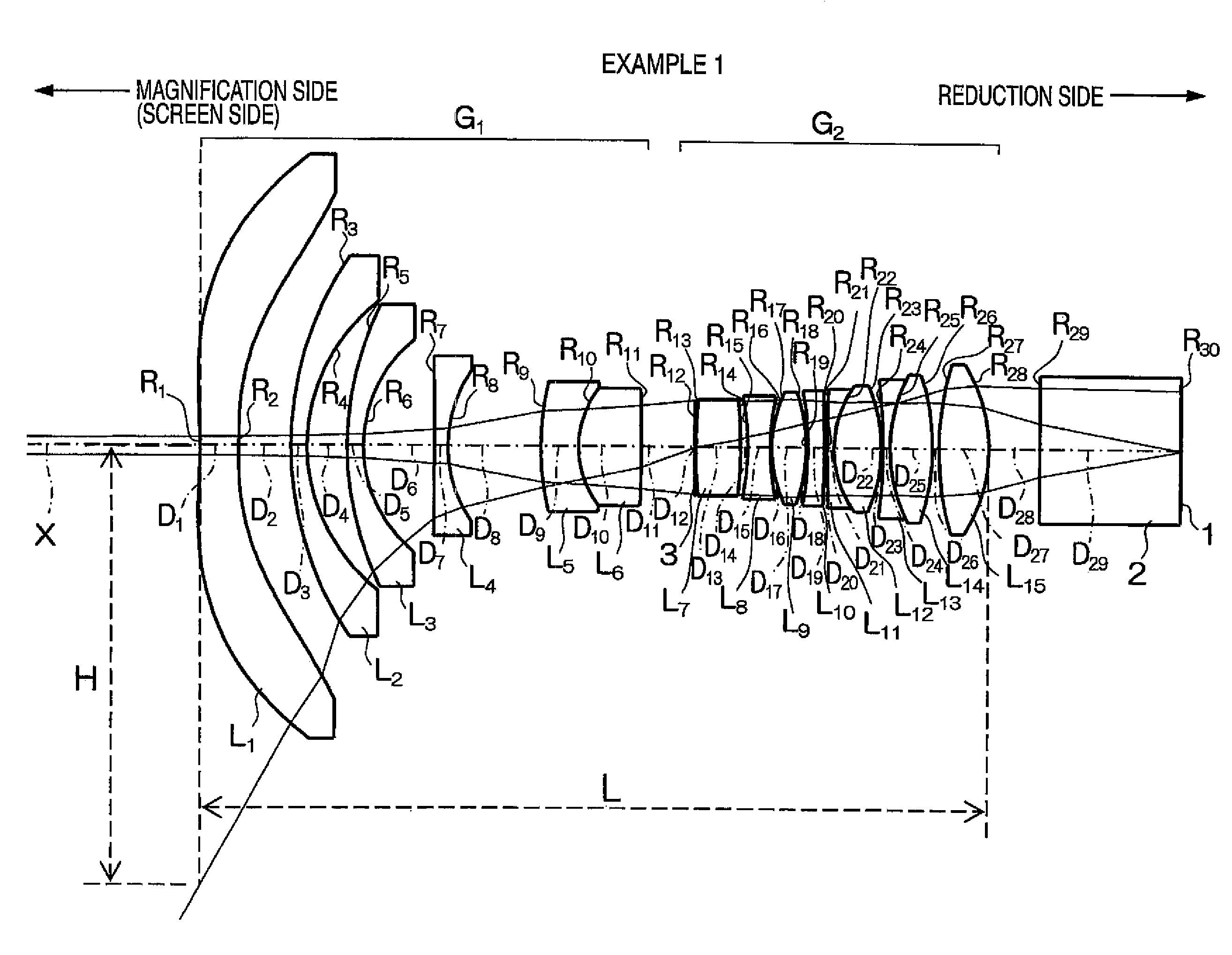
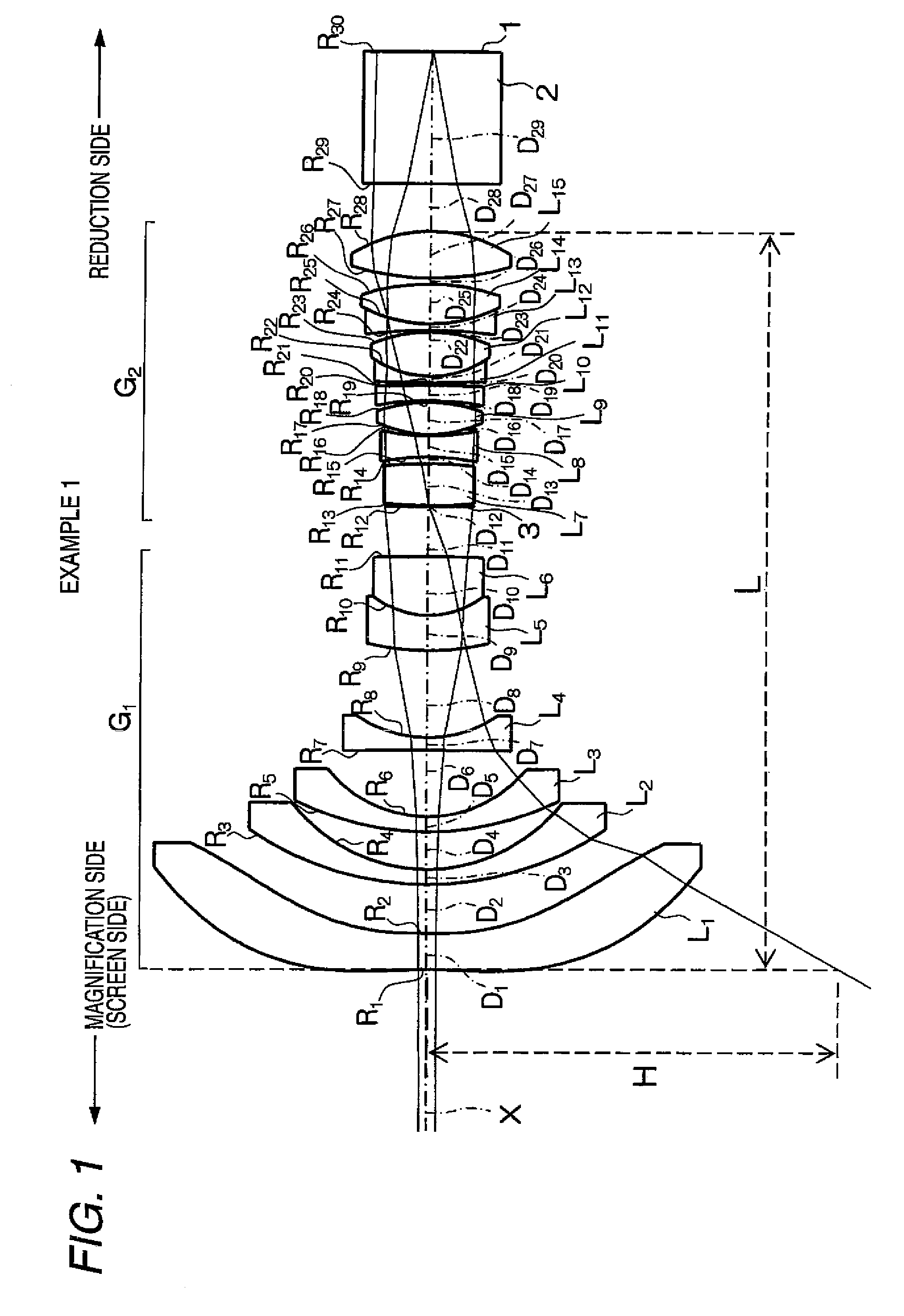
[0071]As shown in FIG. 1, in a projection lens according to an example 1, a first lens group G1 having negative refractive power and a second lens group G2 having positive refractive power are arranged in order from the magnification side. The projection lens is substantially telecentric on the reduction side.

[0072]The first lens group G1 includes, in order from the magnification side, a first lens L1 formed of a plastic aspheric lens having small refractive power (mainly for the purpose of aberration correction), a second lens L2 and a third lens L3 of which each is formed of a negative meniscus lens whose convex surface is directed to the magnification side, a fourth lens L4 formed of a biconcave lens, and a cemented lens formed by two lenses which are a fifth lens L5 formed of a negative meniscus lens whose concave surface is directed to the reduction side and a sixth lens L6 formed by a biconvex lens.

[0073]On the other hand, the second lens group G2 includes a seventh lens L7 fo...

example 2

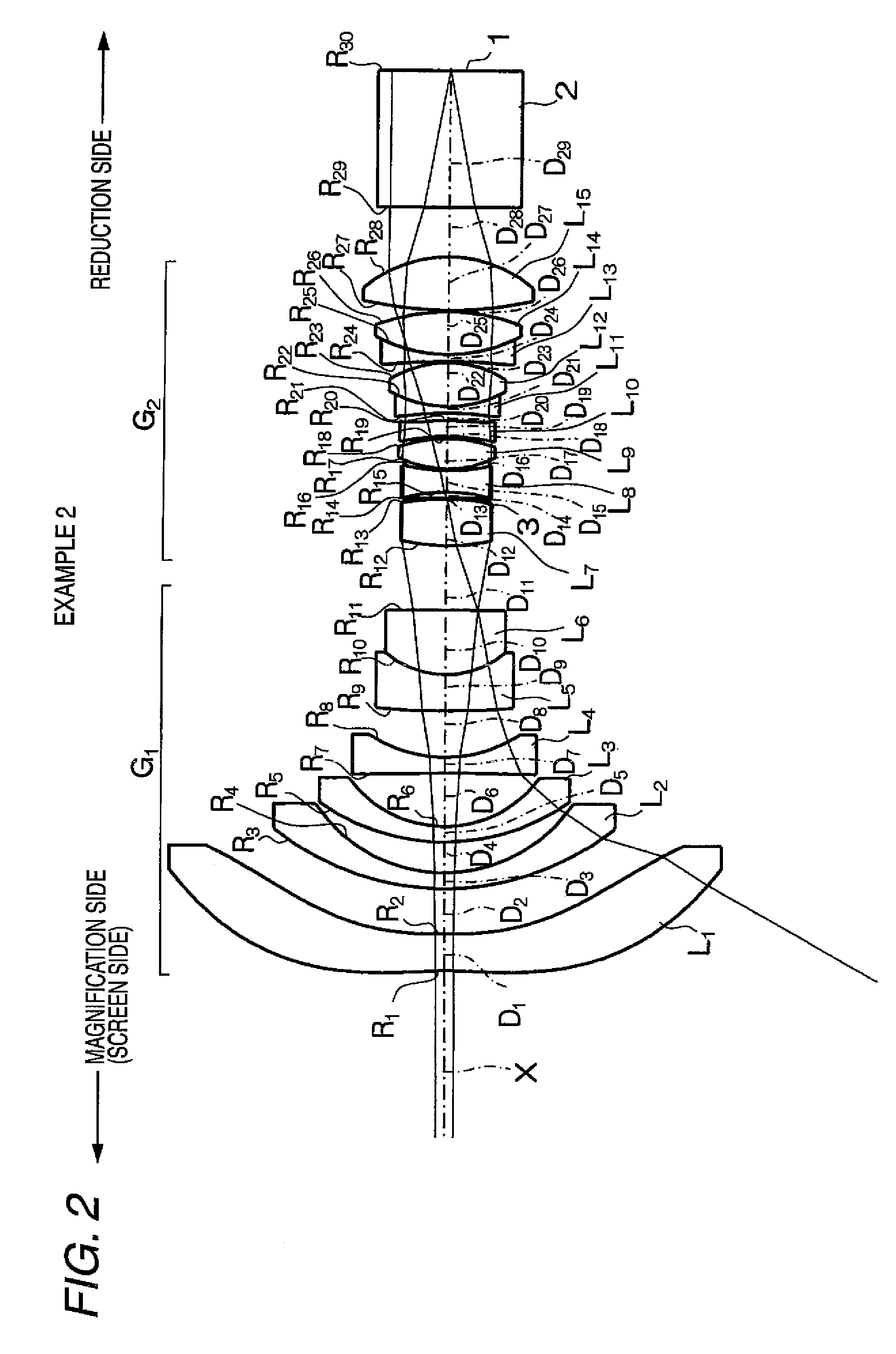
[0080]A projection lens according to an example 2 is as shown in FIG. 2. This projection lens has substantially similar constitution to the constitution of the projection lens in the example 1, and the explanation of the common portions is omitted.

[0081]Namely, the projection lens in the example 2 is different from the projection lens in the example 1 in a point that the aperture diaphragm 3 is disposed between the seventh lens L7 on the most magnification side in the second lens group G2 and the eighth lens t8 located on the reduction side of the seventh lens L7, and in a point that the eleventh lens L11 is a biconcave lens.

[0082]Regarding the projection lens in the example 2, radii R of curvature of respective lens surfaces, on-axis surface spacing D between the respective lenses, and refractive indices Nd and Abbe numbers υd of the respective lenses at the d-line are given on the upper portion of a table 2. Further, values of respective contacts K, and A3 to A12 corresponding to ...

example 3

[0084]A projection lens according to an example 3 is as shown in FIG. 3. This projection lens has substantially similar constitution to the constitution of the projection lens in the example 1, and the explanation of the common portions is omitted. This projection lens is different from the projection lens in the example 1 in a point that in place of the eighth lens LB in the second lens group G2 in the example 1, a cemented lens formed by two lenses which are an eighth lens L8 formed of a biconcave lens and a ninth lens L9 formed of a biconvex lens is provided. Lenses from a tenth lens L10 on in FIG. 3 correspond to the respective lenses in the example 1 whose lens numbers are advanced one by one.

[0085]Regarding the projection lens in the example 3, radii R of curvature of respective lens surfaces, on-axis surface spacing D between the respective lenses, and refractive indices Nd and Abbe numbers υd of the respective lenses at the d-line are given on the upper portion of a table 3....


PUM


Abstract

A projection lens includes, in order form a magnification side: a first lens group having negative refractive power; and a second lens group having positive refractive power. An aspheric lens is arranged on the most magnification side of the first lens group. The conditional expressions 3<Bf/f and 0.4<H/L are satisfied, where f denotes a focal length of the projection lens, Bf denotes an air-converted back focal length, H denotes a height of a principal ray at the maximum angle of view on a plane which is orthogonal to an optical axis and which passes through point A, and L denotes a length from the point A to a vertex of a lens surface on the most reduction side on the optical axis. Here, the point A is a vertex of a lens surface on the most magnification side on the optical axis.

Description

CROSS-REFERENCE TO RELATED APPLICATIONS[0001]This application is based on and claims priority under 35 USC 119 from Japanese Patent Application No. 2007-277606 filed Oct. 25, 2007; the entire contents of which are incorporated herein by reference.BACKGROUND[0002]1. Technical Field[0003]The present invention relates to a projection lens which enlarges and displays display information from a light valve such as liquid crystal display element, and particularly to a projection lens suitable for a front type projection type display device and a projection type display device using the same.[0004]2. Related Art[0005]Recently, a projection type display device using a light valve such as a liquid crystal display device or a DMD display device has been widely spread.[0006]Particularly, there has been widely used a projection type display device which uses three light valves so that the three light values correspond respectively to illumination light of RGB primaries, thereby to modulate thes...

Claims


Application Information

Patent Timeline
Patent Type & Authority Applications(United States)
IPC IPC(8): G02B27/18
CPCG02B13/16
Inventor NAGATOSHI, YUKIKO
Owner FUJI PHOTO OPTICAL CO LTD
Why Eureka
Try Eureka