Flow channel switching valve

a technology of flow channel and switching valve, which is applied in the direction of valve operating means/release devices, instruments, transportation and packaging, etc., can solve the problems of increasing the exchange cost of parts, difficult to remove the stator and the packing from the housing top, and not easy to work for workers, so as to prevent the drop of the stator

Active Publication Date: 2014-09-18
SHIMADZU CORP
View PDF6 Cites 2 Cited by
  • Summary
  • Abstract
  • Description
  • Claims
  • Application Information

AI Technical Summary

Benefits of technology

[0017]Since the flow channel switching valve of the present invention includes the stator fixing member detachably mounted on the housing top from the stator side, and the stator is fixed to the housing top by the stator fixing member, attachment/detachment of the stator fixing member makes attachment/detachment o

Problems solved by technology

However, since fixing the stator and the packing to the housing top by the spring pin or the like makes it difficult to detach the stator and the packing from the housing top, in many cases, when the stator is exchanged, the whole housing top is exchanged in place of exchanging only the st

Method used


Image

  • Flow channel switching valve
  • Flow channel switching valve
  • Flow channel switching valve

Examples


Embodiment Construction

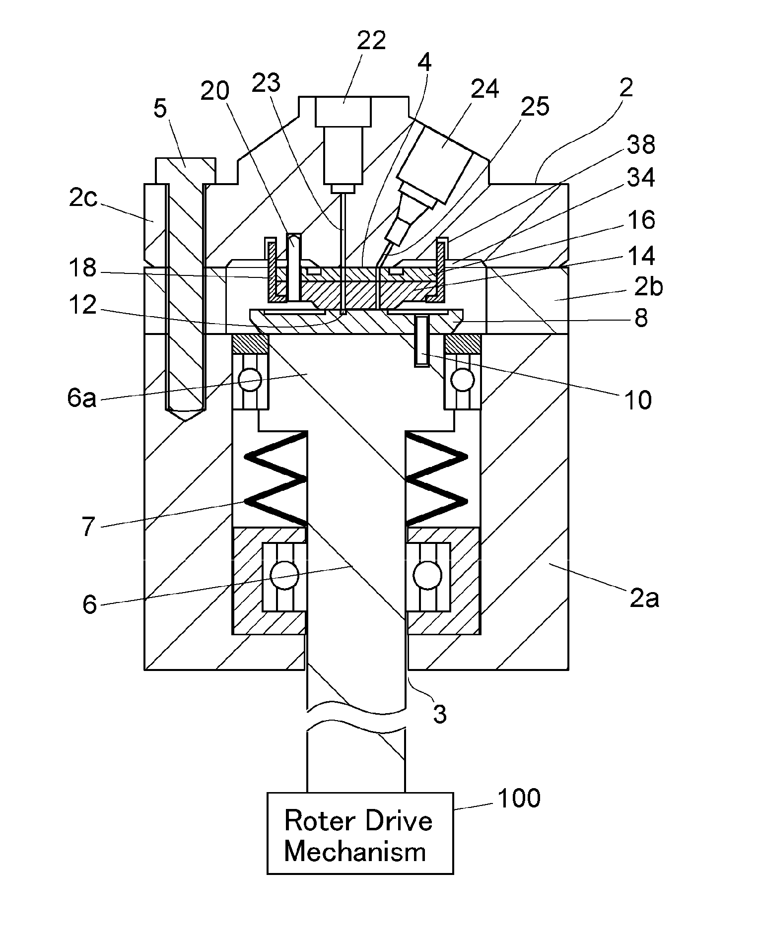
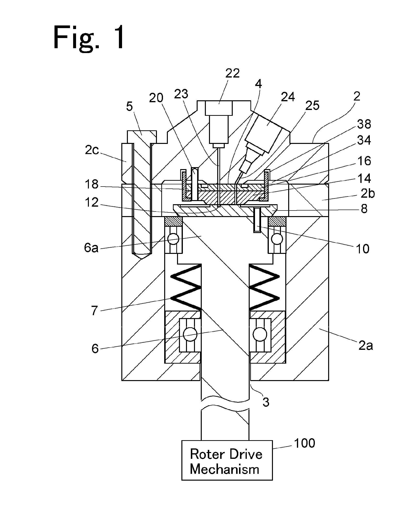
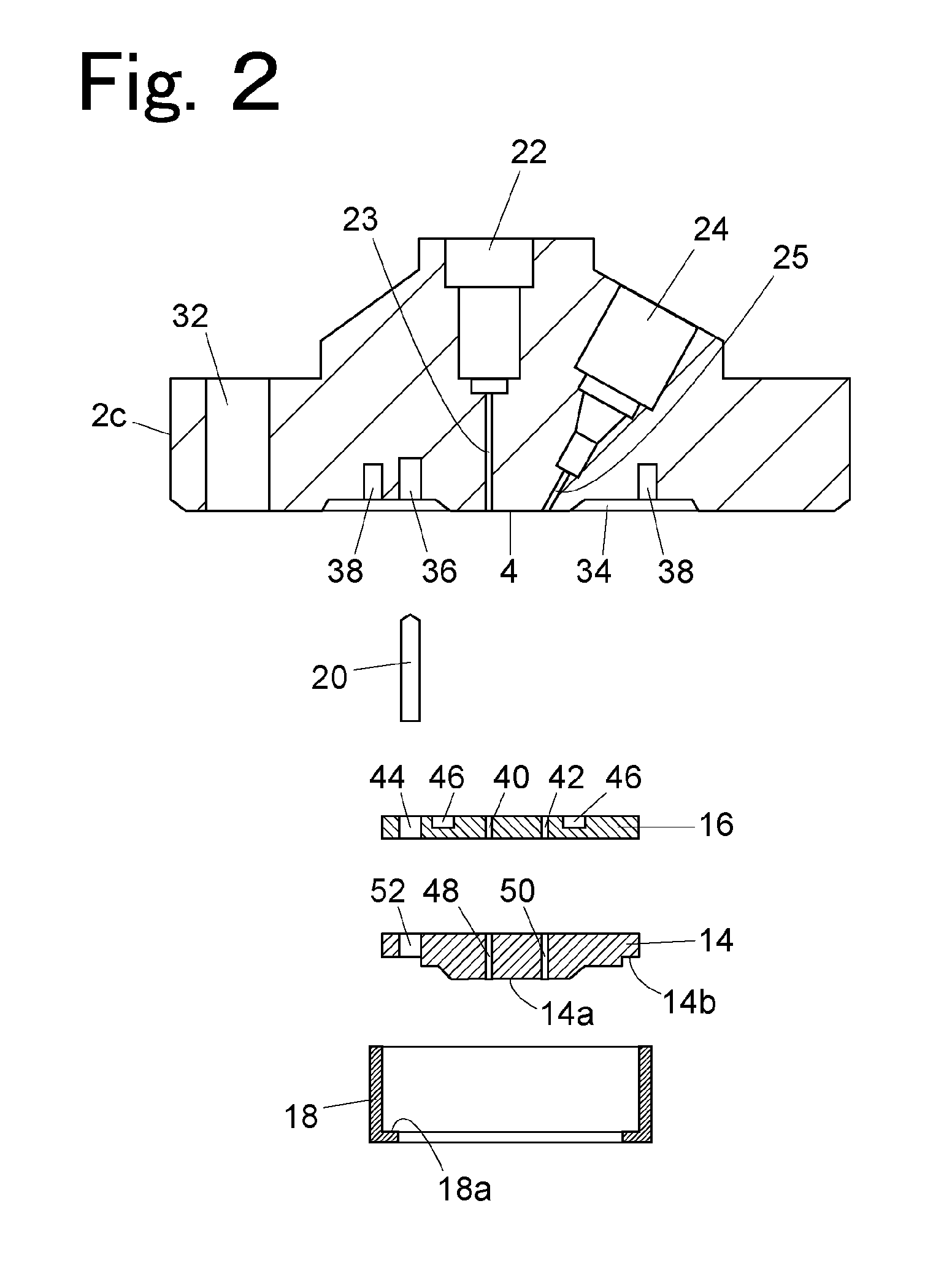
[0020]According to a preferred aspect of the present invention, a stator fixing member is a cylindrical member surrounding an outer circumference of a stator, an engagement portion that engages with a circumferential edge portion of a surface on a rotor side of the stator is provided at one end of the stator fixing member, another end of the stator fixing member is mounted on a housing top, and a circular groove into which the other end of the stator fixing member is fitted is formed around a flow channel connection portion of the housing top. The above-described aspect makes a structure of the stator fixing member and a structure for attaching the stator fixing member to the housing top simple, thereby making easy attachment / detachment work of the stator fixing member by a worker.

[0021]Moreover, in the present invention, it is preferable that a packing that enhances liquid tightness between the stator and the flow channel connection portion is interposed between the stator and the ...


PUM


Abstract

A flow channel switching valve is provided that includes a stator and a rotor inside a housing, and rotates the rotor by a rotor drive portion while sliding the rotor on the stator, wherein the stator is fixed to a housing top by a stator fixing member. The stator fixing member is configured so as to have a portion detachably mounted on the housing top from a stator side, and a portion holding the stator.

Description

BACKGROUND OF THE INVENTION[0001]1. Field of the Invention[0002]The present invention relates to a flow channel switching valve for use in, for example, an auto-sampler that introduces a sample to an analysis flow channel of a liquid chromatograph.[0003]2. Description of the Related Art[0004]As an example, in an auto-sampler that introduces a sample to an analysis flow channel of a liquid chromatograph, after the sample is taken into a sample loop from a sample container, the sample loop is connected to an upstream side of a separation column in the analysis flow channel by switching of a flow channel switching valve, which allows the sample in the sample loop to be transported to a separation column side by a mobile phase flowing in the analysis flow channel.[0005]As the flow channel switching valve for use in the liquid chromatograph, a rotary type switching valve is common. The rotary type switching valve switches a connected flow channel by rotating a rotor (rotary part) (e.g., ...

Claims


Application Information

Patent Timeline
IPC IPC(8): F16K31/04F16K11/065
CPCF16K11/0655F16K31/043F16K11/0743F16K31/041G01N30/20G01N2030/202Y10T137/86622
Inventor TANAKA, SHINJI
Owner SHIMADZU CORP
Why Eureka
Try Eureka