Microphone

a technology for microphones and microphones, applied in the direction of microphone structural association, transducer casings/cabinets/supports, electrical transducers, etc., can solve the problems of device damage, affecting the performance of the speaker, and affecting the sound quality of the speaker, so as to prevent the sliding of the slide member

Active Publication Date: 2017-04-04
AUDIO-TECHNICA
View PDF6 Cites 0 Cited by
  • Summary
  • Abstract
  • Description
  • Claims
  • Application Information

AI Technical Summary

Benefits of technology

[0011]The present invention has been made in view of the foregoing, and an objective is to provide, in a microphone configured such that a microphone head including a microphone unit that performs sound collection is attachably / detachably mounted to a microphone main body, a microphone that enables easy attachment / detachment of the microphone head, and which can perform a mute operation not only after removal of the microphone head but also in attachment / detachment of the microphone head.
[0013]With such a configuration, the mute circuit can be always driven by the switch during attachment / detachment. Therefore, occurrence of the pop noise can be prevented not only after removal of the microphone head from the microphone main body, but also in attachment / detachment of the microphone head.
[0015]With such a bayonet-type coupling system, attachment / detachment of the microphone head becomes easy, and connection between the first mute control circuit and the second mute control circuit can be reliably performed.
[0019]As described above, the slide member is usually covered with the cover member, so that careless sliding of the slide member can be prevented.
[0020]In a microphone configured such that a microphone head including a microphone unit that performs sound collection is attachably / detachably mounted to a microphone main body, a microphone which enables easy attachment / detachment of the microphone head, and which can perform a mute operation not only after removal of the microphone head but also in attachment / detachment of the microphone head can be obtained.

Problems solved by technology

By the way, the microphone configured such that the microphone head is attachably / detachably coupled to the microphone main body as described above have a problem that a pop noise occurs in attachment / detachment.
That is, if the microphone head is attached with / detached from a power source in a power-on state by mistake or on purpose, a large pop noise is caused, and the device may be damaged.
However, in the case of the illustrated screw-type attachment / detachment configuration, the microphone head 52 needs to be relatively rotated with respect to the microphone main body 51 a number of times. Therefore, there are problems that not only labor is required, but also a rubbing noise is output as a noise, until the mute circuit is operated.
Further, there is a problem that the life of contacts becomes short or contact failure is caused due to friction of contacts, by the rotation of the microphone unit a number of times.

Method used


Image

  • Microphone
  • Microphone
  • Microphone

Examples


Embodiment Construction

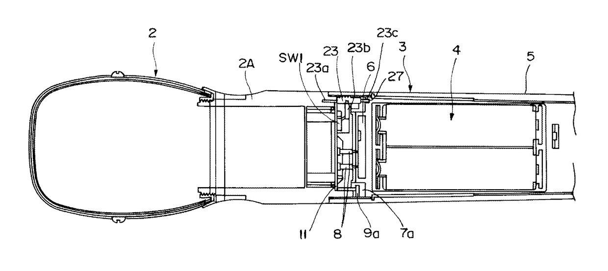
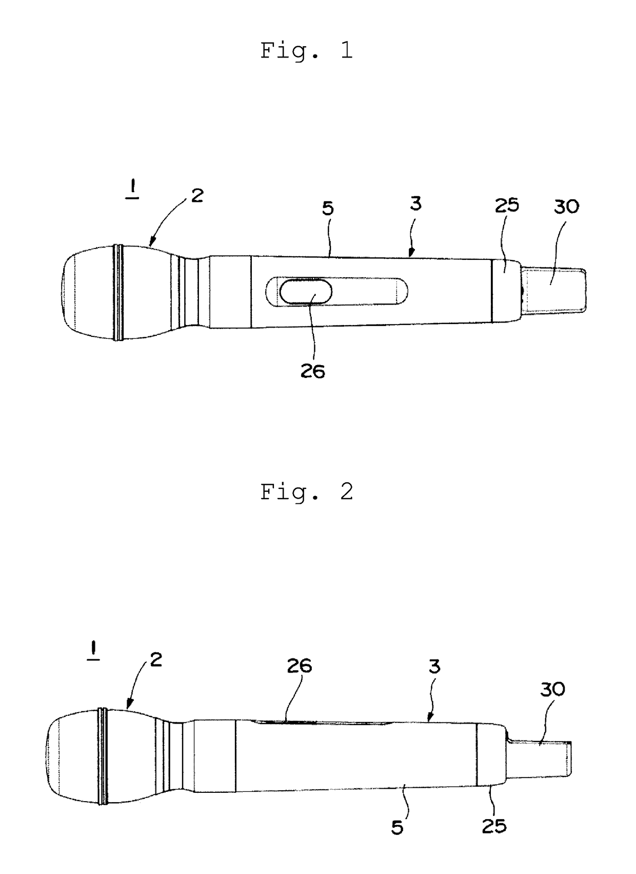
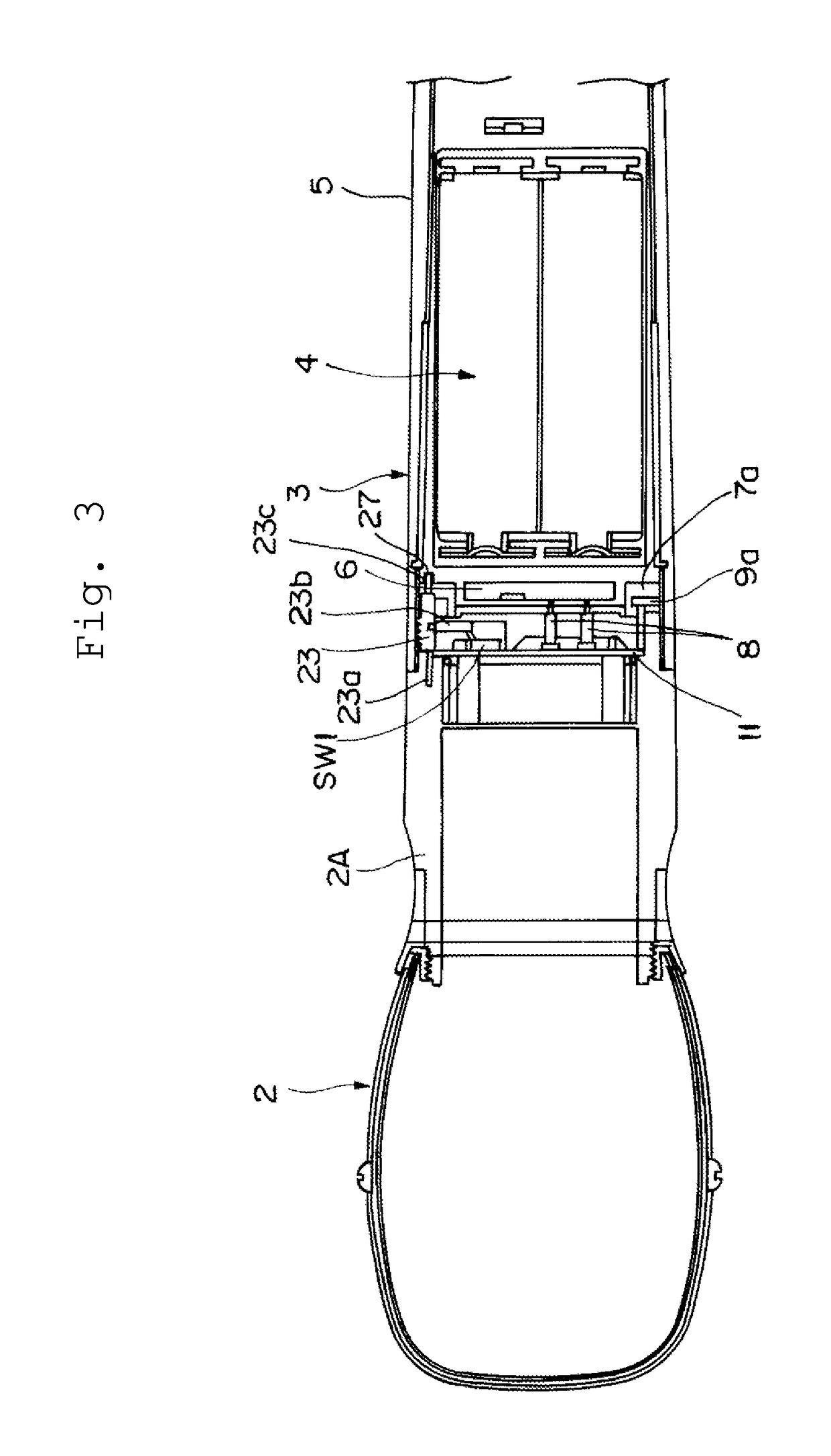
[0030]Hereinafter, embodiments of the present invention will be described based on the drawings. FIG. 1 is a plan view of a microphone according to the present invention, and FIG. 2 is a side view of the microphone. Further, FIG. 3 is a sectional view illustrating an enlarged tip end side of the microphone.

[0031]An illustrated microphone 1 is configured from a microphone head 2 having a microphone unit (not illustrated) built in, the microphone unit performing sound collection, and a microphone main body 3 attachably / detachably provided to the microphone head 2. Note that, in the present embodiment, the microphone 1 illustrated in FIG. 1 is a wireless microphone, and provided with an antenna section 30 at a rear end portion of the microphone main body 3, and a display 26 on an peripheral surface.

[0032]The microphone main body 3 is configured from, as illustrated in FIGS. 1 to 3, an audio substrate (not illustrated), an antenna substrate (not illustrated), a main body member 4 made o...


PUM


Abstract

Provided is, in a microphone configured such that a microphone head including a microphone unit is attachably / detachably mounted to a microphone main body, a microphone which enables easy attachment / detachment of the microphone head, and which can perform a mute operation not only after removal of the microphone head but also in attachment / detachment of the microphone head. The microphone includes a mute circuit provided to a side of the microphone main body, and driven by an input of a mute command signal, a first mute control circuit provided to aside of the microphone head, and including a switch that switches disconnection / conduction of a wire, and a second mute control circuit provided to the side of the microphone main body, and electrically connected with the first mute control circuit and generates the mute command signal, in a state where the microphone head is coupled, and in attachment / detachment of the microphone head.

Description

RELATED APPLICATIONS[0001]The present application is based on, and claims priority from, Japanese Application No. JP2014-231260 filed Nov. 14, 2014, the disclosure of which is hereby incorporated by reference herein in its entirety.BACKGROUND OF THE INVENTION[0002]Field of the Invention[0003]The present invention relates to a microphone configured such that a microphone unit that performs sound collection is attachably / detachably mounted to a microphone main body, and especially relates to a microphone that can be muted in attachment / detachment.[0004]Description of the Related Art[0005]Conventionally, in wired or wireless microphones, there are ones configured such that a microphone head having a microphone unit built in is attachably / detachably coupled to a microphone main body. As a coupling method thereof, a configuration to fix the microphone head and the microphone main body with a special coupling structure, or a configuration to attach / detach a microphone head 52 to a microph...

Claims


Application Information

Patent Timeline
Patent Type & Authority Patents(United States)
IPC IPC(8): H04B15/00H04R1/04H04R3/00H04R1/06
CPCH04R1/04H04R1/06H04R3/00H04R2420/07
Inventor NAITO, YOSHIHIKOMASUDA, AKIRA
Owner AUDIO-TECHNICA
Why Eureka
Try Eureka