
Solution temperature control device in cell observation chamber

a technology of temperature control device and cell observation chamber, which is applied in the field of cell observation chamber temperature control device, can solve the problems of insufficient saying and difficulty in keeping solutions, and achieve the effects of easy operation, improved temperature, and smooth assembly/disassembly operation

Inactive Publication Date: 2011-09-13
HIRATA & CO LTD
View PDF2 Cites 1 Cited by
  • Summary
  • Abstract
  • Description
  • Claims
  • Application Information

AI Technical Summary

Benefits of technology

The present invention provides a solution temperature control device for a cell observation chamber that can keep the solutions in the chamber at a desired constant temperature and improve the accuracy of operations such as detecting cell chemotaxis and isolating chemotactic cells. The device includes a dish-shaped bottom support body with a window for observing cell movement, a glass substrate placed on the bottom support body, a substrate with a plurality of through holes for guiding cell suspension and chemotactic factor containing solution, a packing member with a plurality of through holes for guiding the cell suspension and chemotactic factor containing solution, an intermediate support body with an opening portion formed in the center of the bottom part of the bottom support body, a dish-shaped cover block body with a plurality of through holes for guiding the cell suspension and the chemotactic factor containing solution, and a first temperature controller for measuring the temperature of the solutions and controlling the heating section to be a predetermined preheating temperature. The device also includes a second temperature controller for measuring the temperature of the solutions and controlling the heating section to be a predetermined preheating temperature.

Problems solved by technology

Since the conventional cell observation chamber is thus arranged in such a manner that the solutions filling the wells and the flow path for communicating of the wells in the cell observation chamber 00 are heated from outside the cell observation chamber 00, for example, indirectly through the wall of the bottom support body 01, and that a temperature sensor is installed outside the chamber, it is not easy to keep the solutions at a desired constant temperature, which makes it inadequate to say that the accuracy in controlling the temperature of the solutions is sufficiently given.Patent Document 1: Japanese Patent Laid-Open Publication No. 2002-159287Patent Document 2: Japanese Patent Laid-Open Publication No. 2003-088357

Method used


Image

  • Solution temperature control device in cell observation chamber
  • Solution temperature control device in cell observation chamber
  • Solution temperature control device in cell observation chamber

Examples


Embodiment Construction

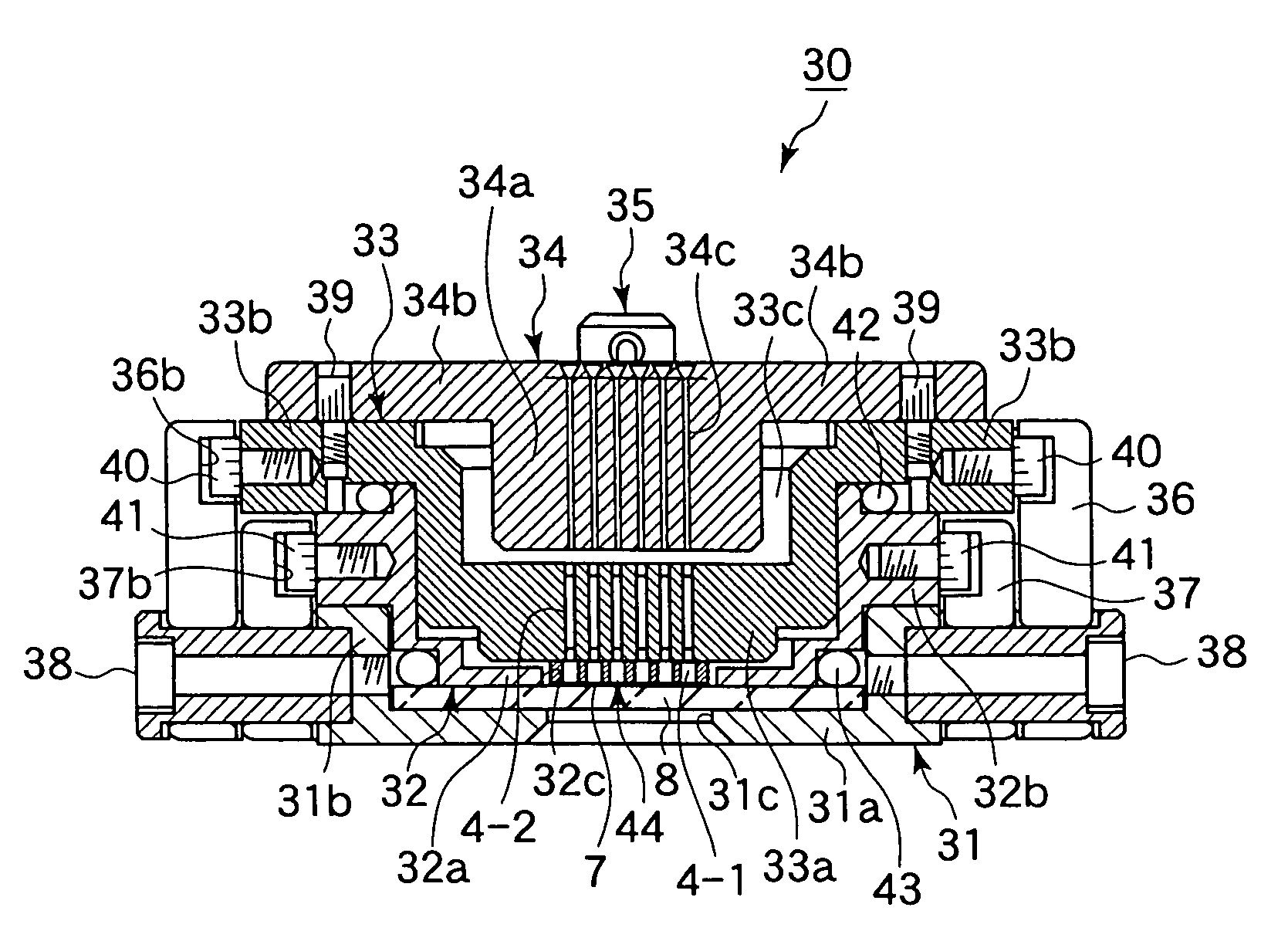
[0040]In order to control the temperature of solutions in a cell observation chamber, it is arranged that a second temperature controller and a first temperature controller are used, the second temperature controller being adapted to measure the temperature of solutions filling a pair of wells and a flow path in the cell observation chamber and to control the solutions to be a predetermined temperature, and the first temperature controller being adapted to measure the temperature of a heating section that heats the cell observation chamber from outside, thereby indirectly heats the solutions filling the pair of wells and the flow path, and to control the heating section to be a predetermined preheating temperature. It is then arranged that a state where cells move from one to the other of the wells through the flow path can be observed and the number of the cells can be measured while keeping the solutions filling the pair of wells and the flow path at the predetermined temperature ...


PUM

PropertyMeasurementUnit
temperatureaaaaaaaaaa

Abstract

A solution temperature control device in a biological cell observing chamber (30) used for the detection of chemotaxis and chemotactic cell separator, comprising a first temperature controller (62) and a second temperature controller (63). The first temperature controller (62) measures the temperature of a solution filled in a pair of wells and a flow passage in the chamber and controls the temperature to a specified temperature, and the second temperature controller (63) measures the temperature of a heating part (64) which heats the chamber (30) from the outside to indirectly heat the solution filled in the pair of wells and the flow passage and controls the temperature to a specified preheat temperature. Since the state and quantity of cells moving from one well to the other through the flow passage while holding the temperature of the solution at a specified temperature can be accurately observed and measured, accuracy for controlling the temperature of the solution can be remarkably increased.

Description

BACKGROUND OF THE INVENTION[0001]1. Field of the Invention[0002]The present invention relates to a solution temperature control device in a cell observation chamber, and specifically to a solution temperature control device in a cell observation chamber adapted to control solutions in the cell observation chamber to be a predetermined temperature in an apparatus used for: for example, determining whether or not cells move in a certain direction by themselves; observing a state where cells move in a certain direction by themselves; measuring the number of cells that have moved in a certain direction by themselves; and isolating cells that move in a certain direction by themselves, that is, an apparatus for detecting cell chemotaxis and for isolating chemotactic cells, and thereby to improve the accuracy of these operations.[0003]2. Description of the Prior Art[0004]There have conventionally been proposed and marketed various kinds of apparatuses for detecting cell chemotaxis and for ...

Claims


Application Information

Patent Timeline
Patent Type & Authority Patents(United States)
IPC IPC(8): C12M1/34C12M3/00C12M1/38G02B21/30G02B21/34
CPCG02B21/30G02B21/34Y10S435/809C12M1/38C12M1/34
Inventor NOGUCHI, KOUICHIMATSUMURA, KAZUYUKIMITSUNAGA, TAKESIKANEGASAKI, SHIRO
Owner HIRATA & CO LTD
Learn More