Conveying device

Inactive Publication Date: 2014-09-18
TOYO TIRE & RUBBER CO LTD
View PDF4 Cites 1 Cited by
  • Summary
  • Abstract
  • Description
  • Claims
  • Application Information

AI Technical Summary

Benefits of technology

[0022]According to this configuration, if the grasping mechanism delivers the grasped rolled-up end to the supply target device, it

Problems solved by technology

However, when the bead filler is wound around the bead wire, a tensile force is generated due to a difference between an inner periphery and an outer periphery of the bead filler, and the tensile force causes problems that the outer periphery of the bead filler is bent or thinned, the bonded portion is peeled off, and cut rubber

Method used


Image

  • Conveying device
  • Conveying device
  • Conveying device

Examples


Embodiment Construction

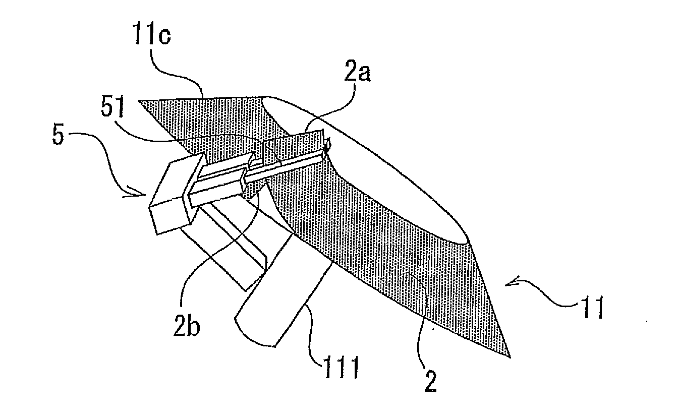
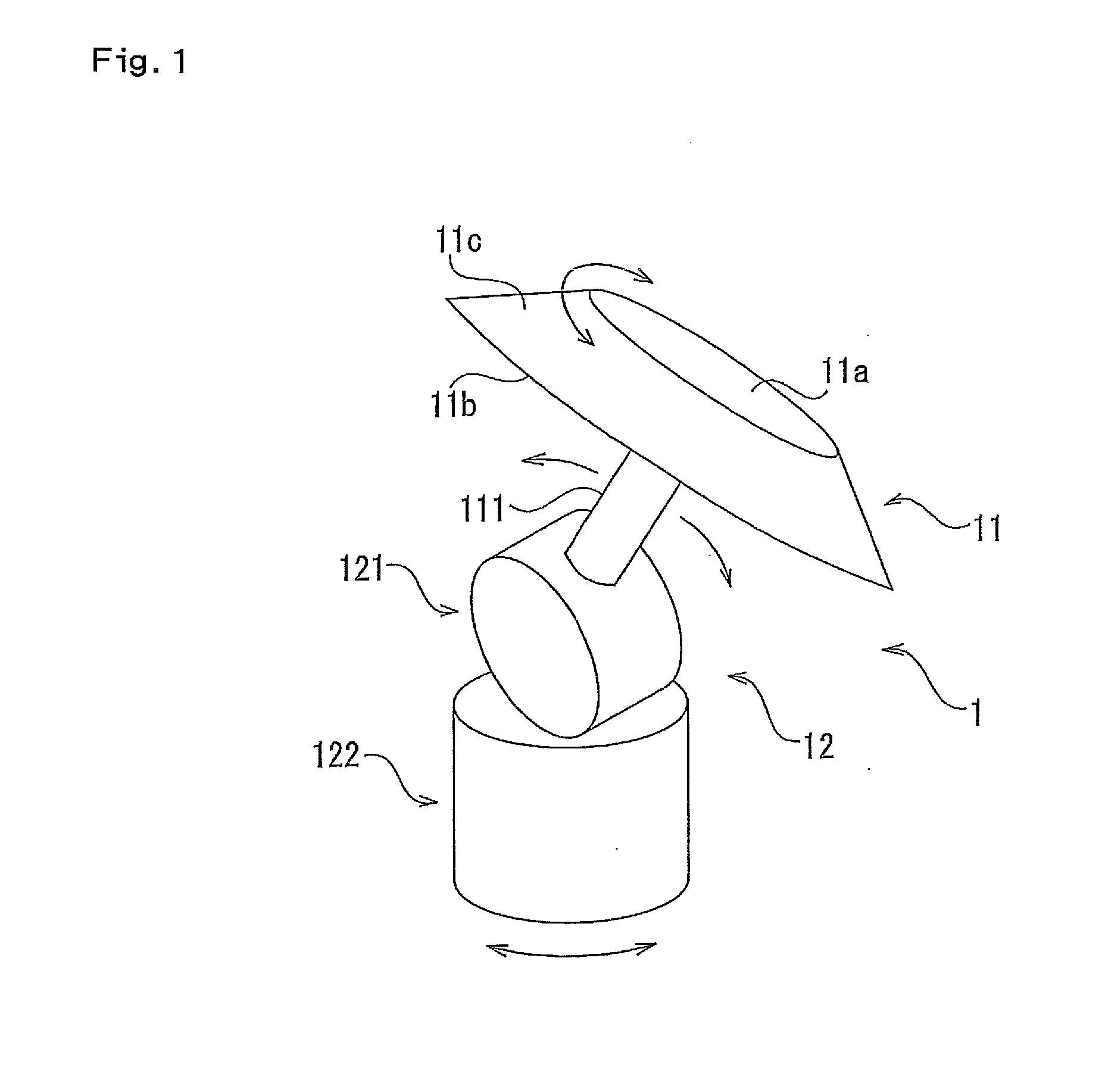
[0030]An embodiment of the present invention will be described below with reference to the drawings. FIG. 1 is a perspective view showing an entire conveying device. A conveying device 1 of the present invention receives a curved rubber member supplied from a supply device, and delivers the rubber member to a supply target device.

[0031]Although a shape of the rubber member is not particularly limited, the conveying device of the present invention is useful in conveying the rubber member which has a thin and wide cross-sectional shape and is curved in a width direction. The present embodiment shows the rubber member extruded from an extrusion device in a curved state, to mold an annular bead filler which is longitudinally long and has a substantially triangular cross section.

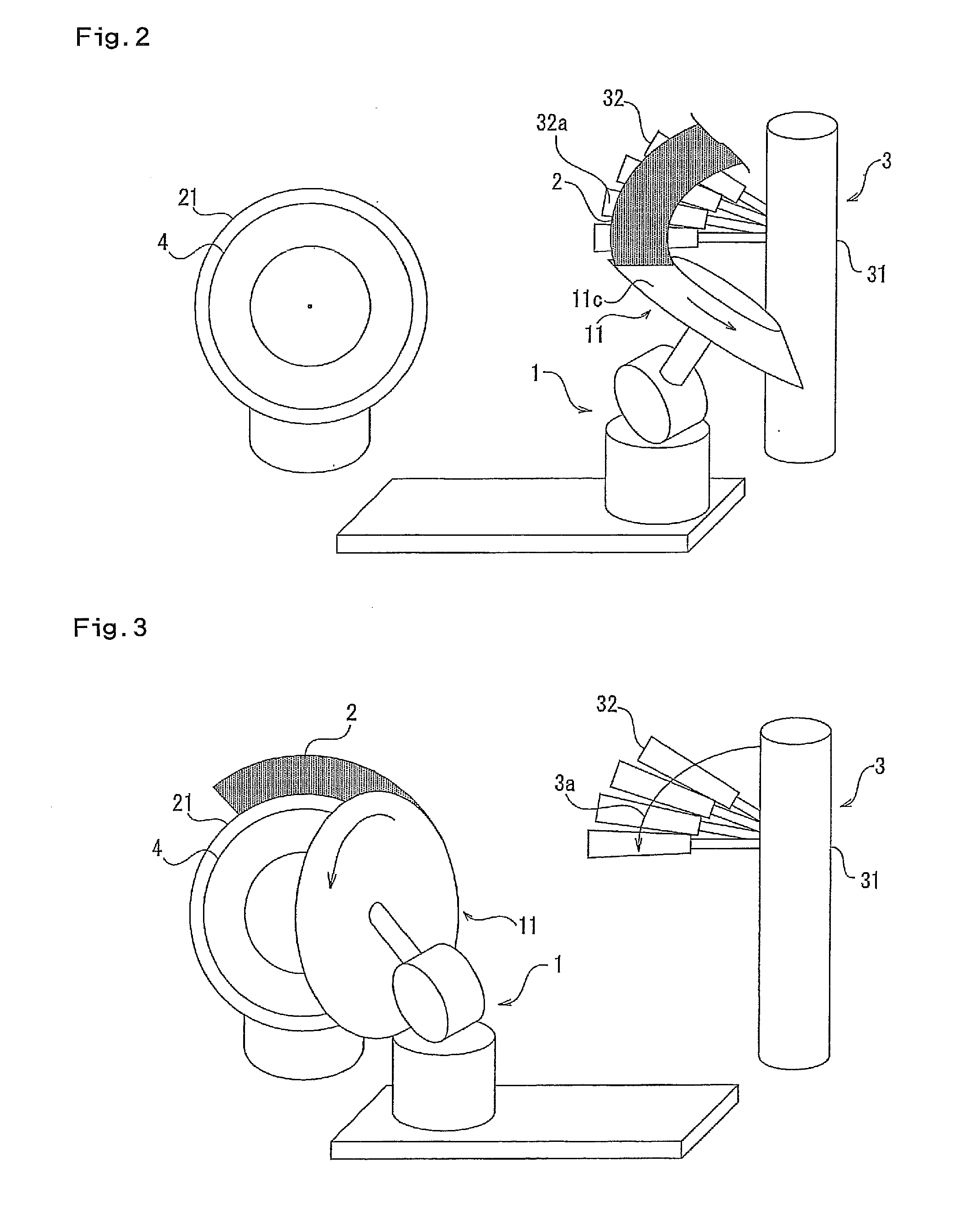
[0032]The conveying device 1 includes a rotary table 11 having an annular mounting surface on which the curved rubber member can be placed, and a moving mechanism 12 capable of moving the rotary table 11 between ...


PUM


Abstract

A conveying device which receives a curved rubber member supplied from a supply device and delivers the rubber member to a supply target device, the conveying device including a rotary table having an annular mounting surface on which the curved rubber member is placed, and a moving mechanism capable of moving the rotary table between a receiving position and a delivery position, wherein the rotary table is rotated at the receiving position to roll up the rubber member, is moved from the receiving position to the delivery position, and is reversely rotated at the delivery position to roll back the rubber member.

Description

BACKGROUND OF THE INVENTION[0001]1. Field of the Invention[0002]The present invention relates to a conveying device that receives a curved rubber member supplied from a supply device and delivers the rubber member to a supply target device.[0003]2. Description of the Related Art[0004]In the manufacture of pneumatic tires, the following method is frequently used when an annular bead filler is molded. That is, a bead filler having a predetermined cross-sectional shape is straightly extruded, the bead filler is wound around an outer peripheral side of a bead wire, and ends thereof are bonded to each other. However, when the bead filler is wound around the bead wire, a tensile force is generated due to a difference between an inner periphery and an outer periphery of the bead filler, and the tensile force causes problems that the outer periphery of the bead filler is bent or thinned, the bonded portion is peeled off, and cut rubber is generated.[0005]In order to solve these problems, in...

Claims


Application Information

Patent Timeline
IPC IPC(8): B29D30/48
CPCB29D30/48B29D2030/482
Inventor MIYAMOTO, RYOSHITSUBOTANI, SOUSUKE
Owner TOYO TIRE & RUBBER CO LTD
Why Eureka
Try Eureka