
V-shaped groove cutting device

A cutting device and cutting mechanism technology, used in metal processing, electrical components, printed circuit manufacturing, etc., can solve the problems of inability to separate small circuit boards, troublesome installation of spare parts, and reduce production efficiency, and achieve stable transportation and improved production efficiency. Work efficiency, stable cutting effect

Pending Publication Date: 2021-04-30
NANJING COLLEGE OF INFORMATION TECH
View PDF5 Cites 0 Cited by
  • Summary
  • Abstract
  • Description
  • Claims
  • Application Information

AI Technical Summary

Problems solved by technology

[0002] In order to improve production efficiency and reduce costs when producing small or micro circuit boards, enterprises will perform imposition operations, that is, there are several small or micro circuit boards on a large circuit board. For such a large circuit board, if after cutting, due to The size of the circuit board is too small, and it will be very troublesome to install the spare parts, but if all the components are installed, it will not be possible to separate the small circuit board from the large circuit board, which will reduce the production efficiency

Method used


Image

  • V-shaped groove cutting device
  • V-shaped groove cutting device
  • V-shaped groove cutting device

Examples


Embodiment Construction

[0020] The implementation of the technical solution will be further described in detail below in conjunction with the accompanying drawings. The following examples are only used to illustrate the technical solution of the present invention more clearly, but not to limit the protection scope of the present invention.

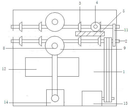
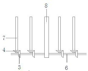
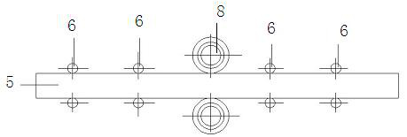
[0021] Such as Figure 1~4 One embodiment shown is a V-shaped groove cutting device, comprising: a box body 1, a transmission mechanism, a cutting mechanism, a first driving mechanism 13 and a second driving mechanism 14, the transmission mechanism, the cutting mechanism and the driving mechanism They are respectively fixed inside the box body 1. The transmission mechanism includes two rotating shafts 2 arranged in parallel up and down. The rotating shafts 2 are connected with the first driving mechanism 13, and a plurality of first cones are evenly arranged coaxially on each of the rotating shafts 2. gear 3, and each first bevel gear 3 meshes with the second be...


PUM


Abstract

The invention discloses a V-shaped groove cutting device which comprises a box body, a transmission mechanism, a cutting mechanism, a first driving mechanism and a second driving mechanism. The transmission mechanism, the cutting mechanism and the driving mechanisms are fixed to the inner side of the box body; the transmission mechanism comprises two rotating shafts arranged in parallel up and down; each rotating shaft is provided with bevel gears for transmission; second bevel gears are used to drive products to move along the length of the rotating shafts; cutting devices are arranged on the two sides of the upper lines of the rotating shafts respectively and used for cutting the products from the upper side and the lower side; the cutting devices are connected with the second driving mechanism; and a plurality of conveying rollers are arranged on the lower sides of the products and are perpendicular to the rotating shafts. According to the V-shaped groove cutting device provided by the invention, after a large circuit board is machined, a V-shaped cutting mode is adopted, one third of the thickness of the circuit board is cut on the upper surface and the lower surface of the circuit board respectively, so that the circuit board is ensured to be still a whole board; and after spare and accessory parts are well installed and the products are delivered to a product assembling enterprise, the small circuit board can be broken off and detached through slight manual force, so that the work efficiency is improved.

Description

technical field [0001] The invention discloses a V-shaped groove cutting device, which relates to the field of mechanical equipment. Background technique [0002] In order to improve production efficiency and reduce costs when producing small or micro circuit boards, enterprises will perform imposition operations, that is, there are several small or micro circuit boards on a large circuit board. For such a large circuit board, if after cutting, due to If the size of the circuit board is too small, it will be very troublesome to install the spare parts, but if all the components are installed, it will not be possible to separate the small circuit board from the large circuit board, which will reduce the production efficiency. Contents of the invention [0003] The present invention aims at the defects in the above-mentioned background technology, and provides a V-shaped groove cutting device with a simple structure. [0004] In order to achieve the above object, the techni...

Claims


Application Information

Patent Timeline
IPC IPC(8): B26D3/06B26D7/02B26D7/06B26D7/18H05K3/00
CPCB26D3/065B26D7/025B26D7/06B26D7/1863H05K3/0044B26F2210/08
Inventor 周志近孙志强
Owner NANJING COLLEGE OF INFORMATION TECH
Learn More