Connector and connector bar

a technology of connectors and connectors, applied in the direction of connection, electrical apparatus, coupling device connections, etc., can solve the problems of electric power affecting the human body and the operation of electronic components, and achieve the effect of safe supply of electric power

Inactive Publication Date: 2014-09-18
FUJITSU COMPONENENT LTD +1
View PDF6 Cites 2 Cited by
  • Summary
  • Abstract
  • Description
  • Claims
  • Application Information

AI Technical Summary

Benefits of technology

[0010]An embodiment of the present invention provides a connector and a connector bar that support a direct-current power supply or a power supply with a voltage higher than the voltage of an existing commercial power supply, and that can safely supply electric power from such a power supply.

Problems solved by technology

On the other hand, when electric power supplied to an electric apparatus has a high voltage, the electric power may affect the human body and operations of electronic components.

Method used


Image

  • Connector and connector bar
  • Connector and connector bar
  • Connector and connector bar

Examples


first embodiment

Configuration of Connector

[0046]A configuration of a connector according to a first embodiment is described. A connector of the present embodiment is to be connected to another connector, which is a plug connector illustrated by FIGS. 1 through 5, and corresponds to a jack connector whose configuration is illustrated by FIGS. 6 through 21. The plug connector illustrated by FIGS. 1 through 5 and the connector corresponding to the jack connector illustrated by FIGS. 6 through 21 may be collectively referred to as a “connector set”.

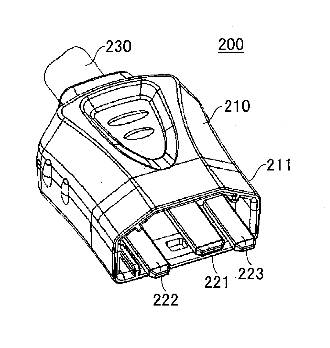
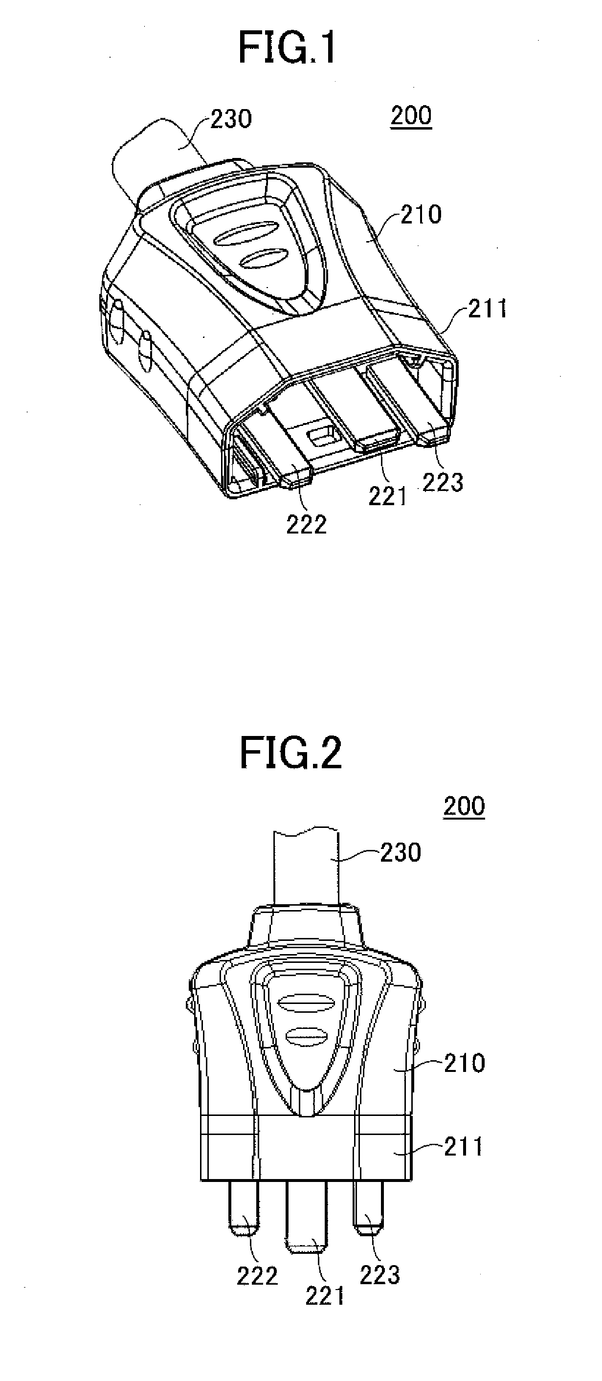
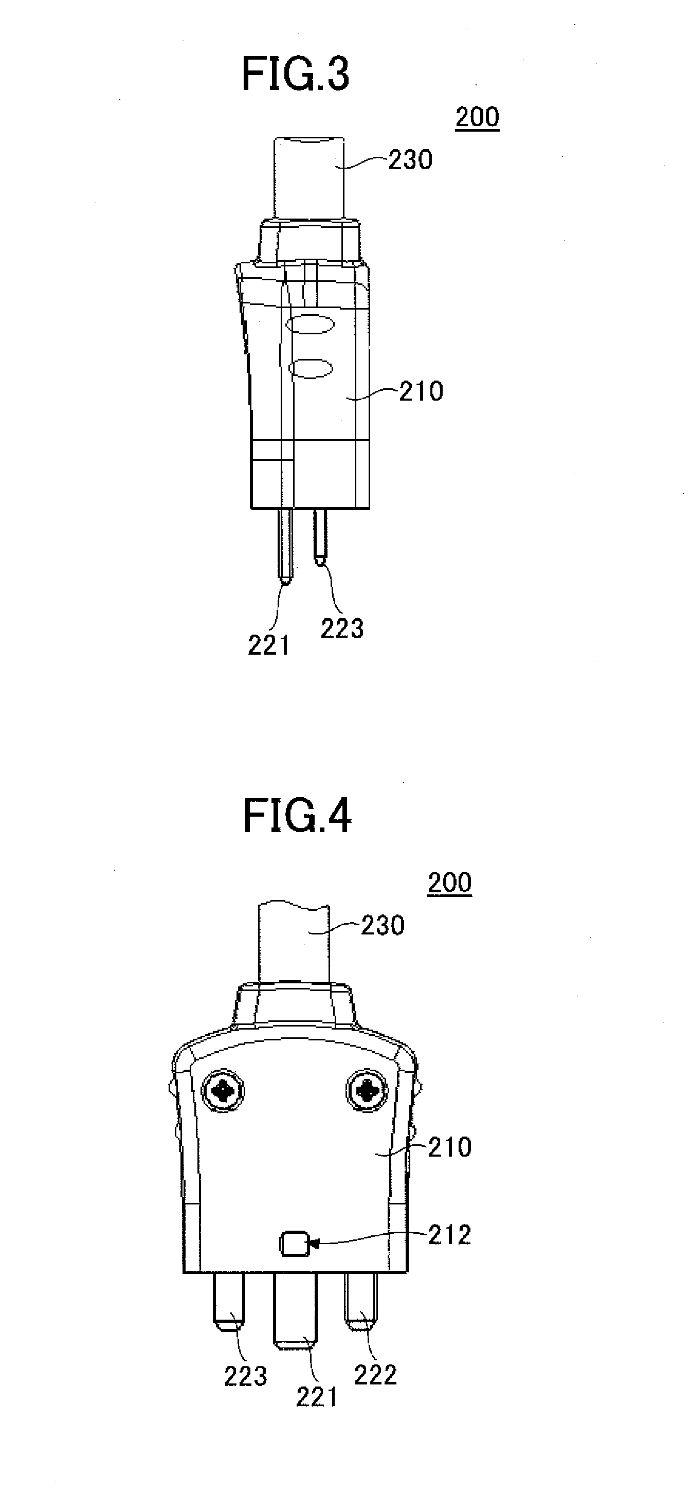
[0047]First, a plug connector 200 is described with reference to FIGS. 1 through 5. FIG. 1 is a perspective view, FIG. 2 is a top view, FIG. 3 is a side view, FIG. 4 is a bottom view, and FIG. 5 is a front view of the plug connector 200. The plug connector 200 includes a cover 210 composed of, for example, an insulator and three plug terminals 221, 222, and 223 that are referred to as “other connecting terminals”. A power cable 230 is connected to a side of...

second embodiment

[0064]Next, a second embodiment is described. A connector bar 300 of the second embodiment includes multiple connectors 10a having a configuration similar to that of the connector 10 of the first embodiment, and a housing 320 covering the connectors. The connector bar 300 is connected to a power cable 330. As illustrated by FIGS. 25 through 27, the connectors 10a having a configuration similar to that of the connector 10 of the first embodiment are arranged one-dimensionally in the housing 320 such that sliding operation parts 40a are arranged on the same surface. FIG. 25 is a perspective view, FIG. 26 is a top view, and FIG. 27 is an exploded perspective view of the connector bar 300 of the present embodiment. FIG. 28 is a perspective view of the connector 10a of the connector bar 300 of the present embodiment. In FIGS. 25 and 27, the power cable 330 is omitted. The housing 320 includes a lower housing part 321 and an upper housing part 322. The upper housing part 322 has openings ...


PUM


Abstract

A connector includes a connecting terminal, a fixed contact, a movable plate, a movable contact provided at an end of the movable plate, a card that includes an insulator and contacts the movable plate, a button that contacts the card, an opening spring connected to the button, and a sliding operation part that controls a contact between the fixed contact and the movable contact. When the sliding operation part is moved in a first direction, the movable contact is brought into contact with the fixed contact and the connector is turned on. When the sliding operation part is moved in a second direction opposite to the first direction, the movable contact is caused to move away from the fixed contact and the connector is turned off. The sliding operation part is provided on a surface that is different from a surface on which the connecting terminal is provided.

Description

TECHNICAL FIELD[0001]The present invention relates to a connector and a connector bar.BACKGROUND ART[0002]Generally, an electric apparatus is driven by electric power supplied from a power supply. An electric apparatus typically receives electric power via a connector from a power supply. Patent documents 1 and 2 disclose a connector unit including a protruding male connector and a hollow female connector that are fitted together to be electrically connected.[0003]In recent years, as a measure to cope with global warming, it is being considered to use, even for power transmission in local areas, a direct-current high-voltage power that suffers less power loss during voltage conversion and power transmission and does not necessitate increasing the diameter of a cable. Supplying electric power in this manner is particularly preferable for an information apparatus such as a server that consumes a large amount of electric power.[0004]On the other hand, when electric power supplied to an...

Claims


Application Information

Patent Timeline
Patent Type & Authority Applications(United States)
IPC IPC(8): H01R13/71
CPCH01R13/71H01R13/7132H01R25/003H01H1/26H01H9/443H01H13/52H01H15/24H01H15/102
Inventor BEAK, SEUNGSEOKKIRYU, KOICHIYUBA, TAKASHIIWAMOTO, DAIEINAKAMURA, AKIONORITAKE, MASATOSHIHIROSE, KEIICHI
Owner FUJITSU COMPONENENT LTD
Why Eureka
Try Eureka