Axial-flow fan

a technology of axial flow and fan blade, which is applied in the direction of liquid fuel engines, vessel construction, marine propulsion, etc., can solve the problems of narrowing of a space and the possibility of molding failure in the outer perimeter portion of the blad

Inactive Publication Date: 2014-11-20
DAIKIN IND LTD
View PDF0 Cites 18 Cited by
  • Summary
  • Abstract
  • Description
  • Claims
  • Application Information

AI Technical Summary

Benefits of technology

[0026]The inflow of resin to the indented part and the vicinity thereof is thereby ensured during molding and molding failure in the indented part and the vicinity thereof can be minimized, despite the fact that both the first blade thinned-out part and the indented part are formed in this axial-flow fan.

Problems solved by technology

However, formation of the thinned-out part in the joint of the blade leads to narrowing of a space in which the resin injected into the mold flows toward the outer perimeter side during molding of the axial-flow fan.
Therefore, in the axial-flow fan having the thinned-out part formed in the joint of the blade, the resin does not readily flow into a portion further toward the outer perimeter side from the thinned-out part during molding, and there is a possibility that molding failure might occur in the outer perimeter portion of the blade.

Method used


Image

  • Axial-flow fan
  • Axial-flow fan
  • Axial-flow fan

Examples


Embodiment Construction

[0038]An embodiment of the axial-flow fan according to the present invention is described below based on the accompanying drawings. The specific configuration of the axial-flow fan according to the present invention is not limited to the embodiment below, and modifications are possible within a scope not deviating from the main point of the present invention. In the description below, an example in which the present invention is applied to an axial-flow fan configuring an outdoor unit is described, but the present invention is not limited to this; it may be applied to an axial-flow fan for another use.

[0039](1) Overall Configuration of the Outdoor Unit

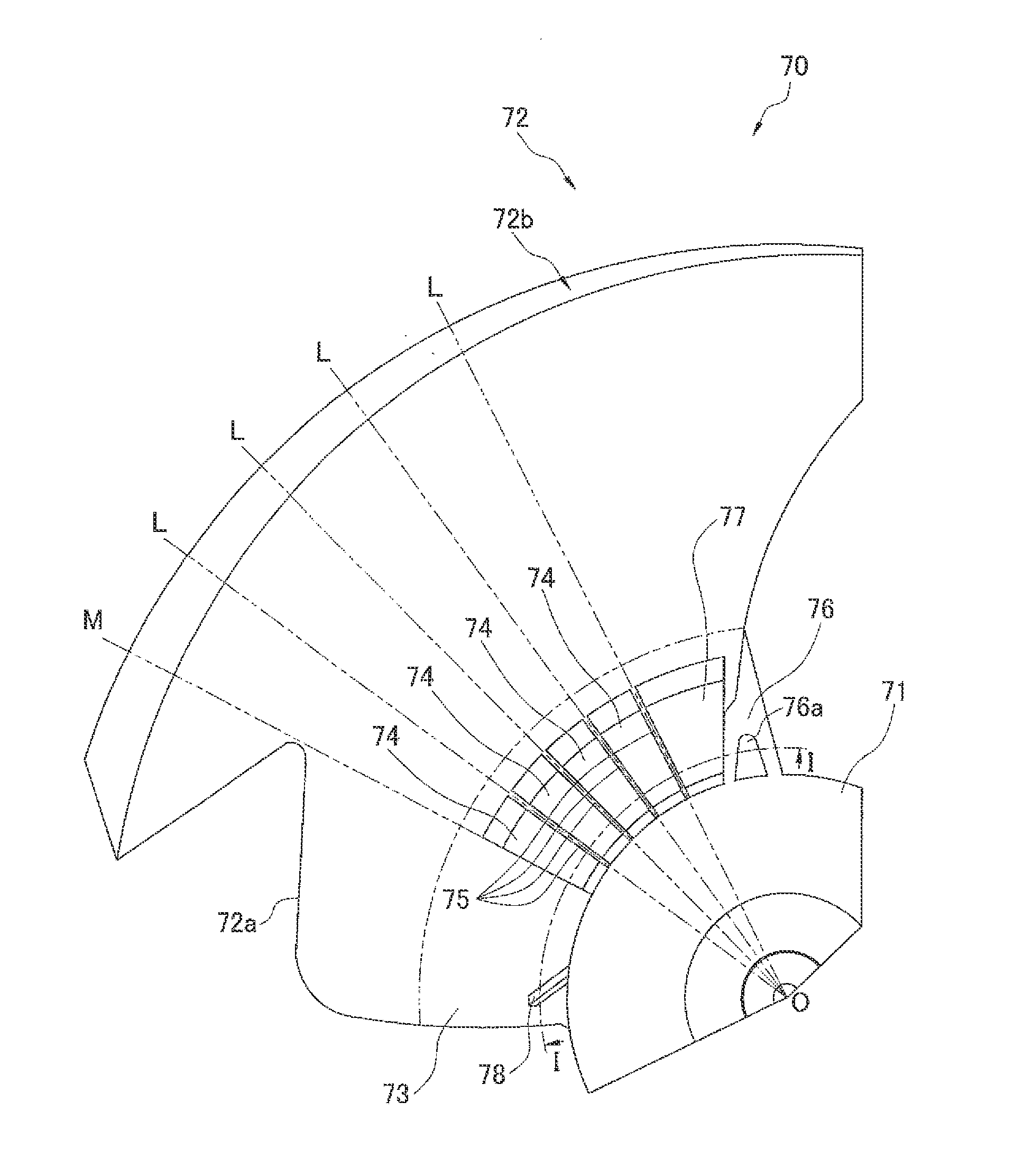
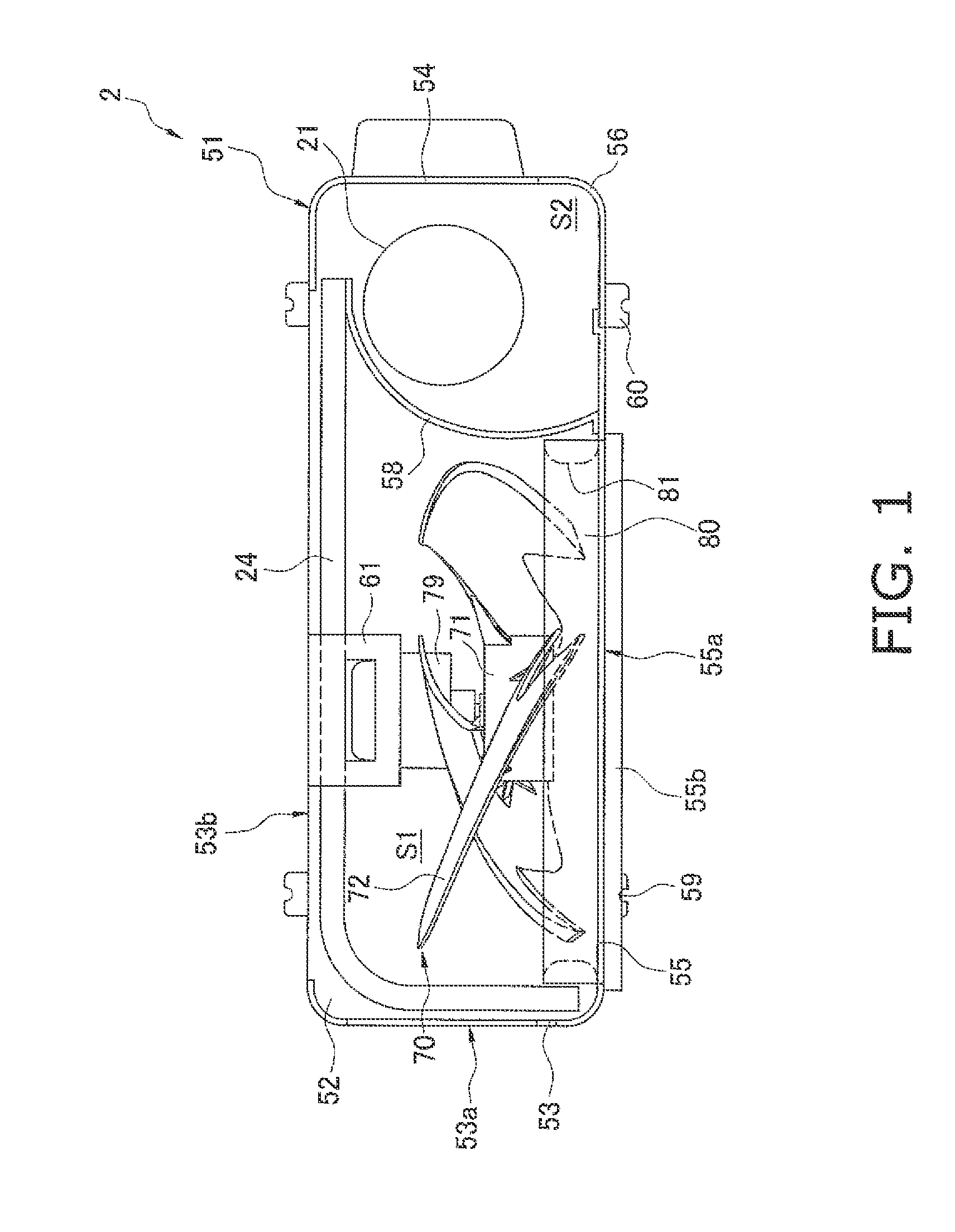
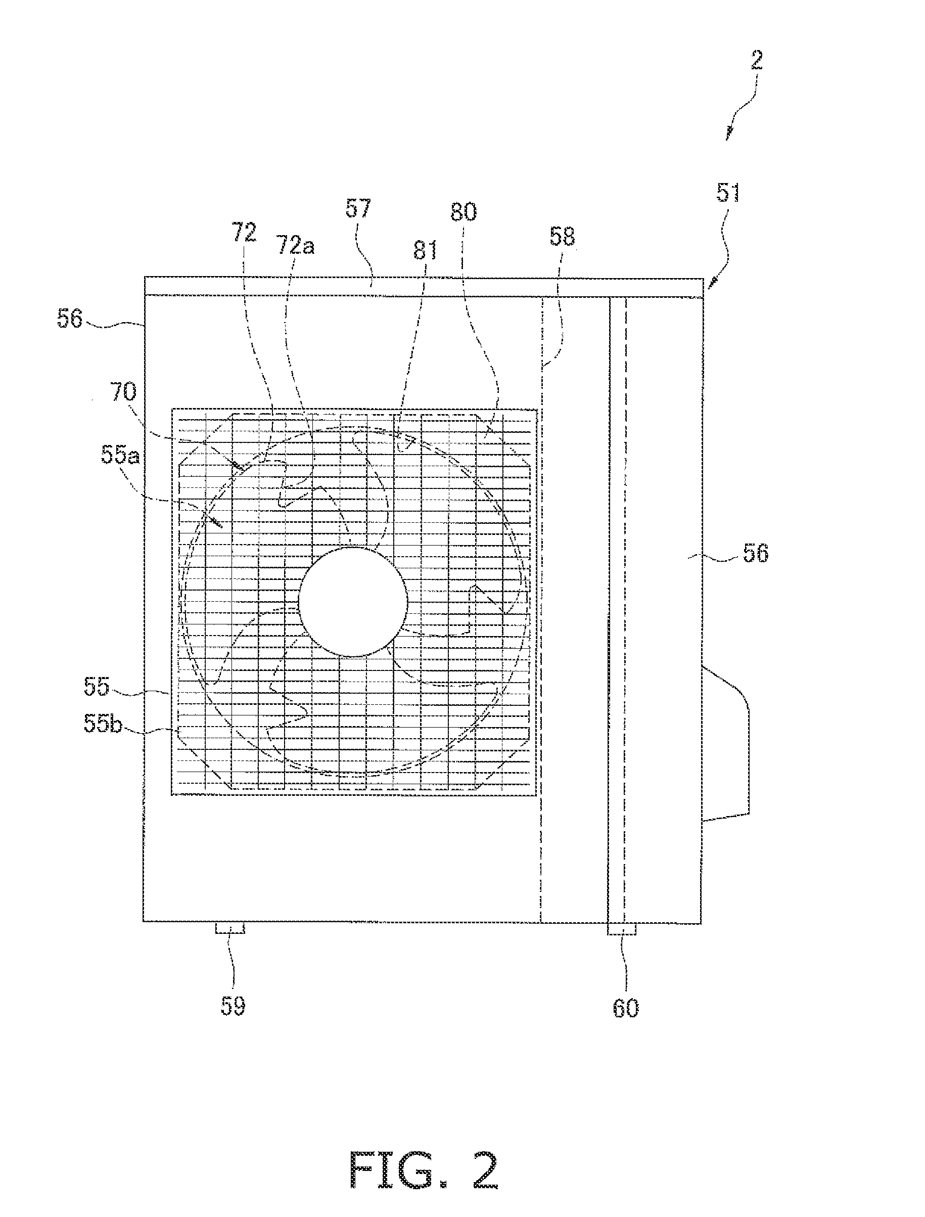
[0040]FIGS. 1 and 2 are drawings illustrating an outdoor unit 2 of an air conditioning apparatus in which is adopted an outdoor fan 70 as an axial-flow fan according to one embodiment of the present invention. Here, FIG. 1 is a plan view of the outdoor unit 2 in a condition having removed a ceiling plate 57. FIG. 2 is a front view of t...


PUM


Abstract

An axial-flow fan includes a hub and a plurality of blades integrally resin-molded to the hub at a plurality of joints, The plurality of blades are formed so as to project from an outer perimeter edge of the hub. Each joint has at least one first blade thinned-out part formed so that at least one radial rib extending radially toward an outer perimeter side is formed.

Description

TECHNICAL FIELD[0001]The present invention relates to an axial-flow fan, and relates in particular to an axial-flow fan with which a hub and a plurality of blades are integrally resin-molded, the blades being formed so as to project from an outer perimeter edge of the hub.BACKGROUND ART[0002]An axial-flow fan with which a hub and a plurality of blades are integrally resin-molded, the blades being formed so as to project from an outer perimeter edge of the hub has hitherto been used in an outdoor unit, or the like, of an air conditioning apparatus.[0003]One such axial-flow fan has a thinned-out part formed in a joint of the blade with the hub, as illustrated in patent document 1 (Japanese Unexamined Patent Application Publication No. 2011-74817).SUMMARY OF THE INVENTION[0004]However, formation of the thinned-out part in the joint of the blade leads to narrowing of a space in which the resin injected into the mold flows toward the outer perimeter side during molding of the axial-flow ...

Claims


Application Information

Patent Timeline
Patent Type & Authority Applications(United States)
IPC IPC(8): F04D29/32F04D19/00
CPCF04D19/002F04D29/325F04D29/023F04D29/388F04D29/164F05D2300/43F05D2230/53
Inventor KOJIMA, AZUMIYOKOYAMA, YUUTA
Owner DAIKIN IND LTD
Why Eureka
Try Eureka