Cervical plate system

a cervical spine and plate technology, applied in the field of surgery, can solve the problems of inadvertent destruction of the end plate, inability to fully absorb the blood, so as to achieve the effect of minimizing failur

Inactive Publication Date: 2011-06-21
UNIV OF SOUTH FLORIDA
View PDF29 Cites 17 Cited by
  • Summary
  • Abstract
  • Description
  • Claims
  • Application Information

AI Technical Summary

Benefits of technology

[0007]The invention includes an anti-subsidence, anti-translocation, fusion compression cervical plate system with interface visualization, drill guide and temporary pin. In one embodiment the invention provides a vertebral plate for minimizing the ability of an inter-body cage, filled with bone (or BMP-soaked sponges, etc.), to telescope into the vertebral body and to minimize failure due to cages that telescope into adjacent vertebral bodies on a delayed basis after surgery, as well as creation of reverse lordosis due to such telescoping. Another embodiment provides method to reduce the gap between the inter-body cage and the vertebral body end plate intra-operatively using compression from the plate caused by an offset between the screw bores on the plate and the drill holes, as established with an asymmetric drill guide.

Problems solved by technology

A common problem with the use of any cervical plate in conjunction with inter-body cages is that the cages telescope or subside into adjacent vertebral bodies on a delayed basis after surgery.
This is due to a variety of factors including differences in biomechanical properties of the cage in relation to the vertebral body, inadvertent destruction of the end plate during end plate preparation, poor bone quality and micromotion, among others.
If subsidence becomes too great, screws will break and the plate will fail.
A second problem is that the superior vertebral body may translocate anteriorly on a rotational basis, with the anterior inferior cage serving as the fulcrum; anterior rotational translocation.

Method used


Image

  • Cervical plate system
  • Cervical plate system
  • Cervical plate system

Examples


Embodiment Construction

[0026]In the following detailed description of the preferred embodiments, reference is made to the accompanying drawings, which form a part hereof, and within which are shown by way of illustration specific embodiments by which the invention may be practiced. It is to be understood that other embodiments may be utilized and structural changes may be made without departing from the scope of the invention.

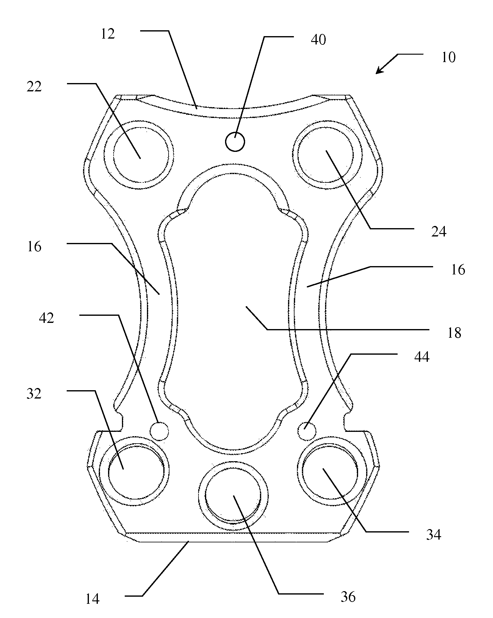
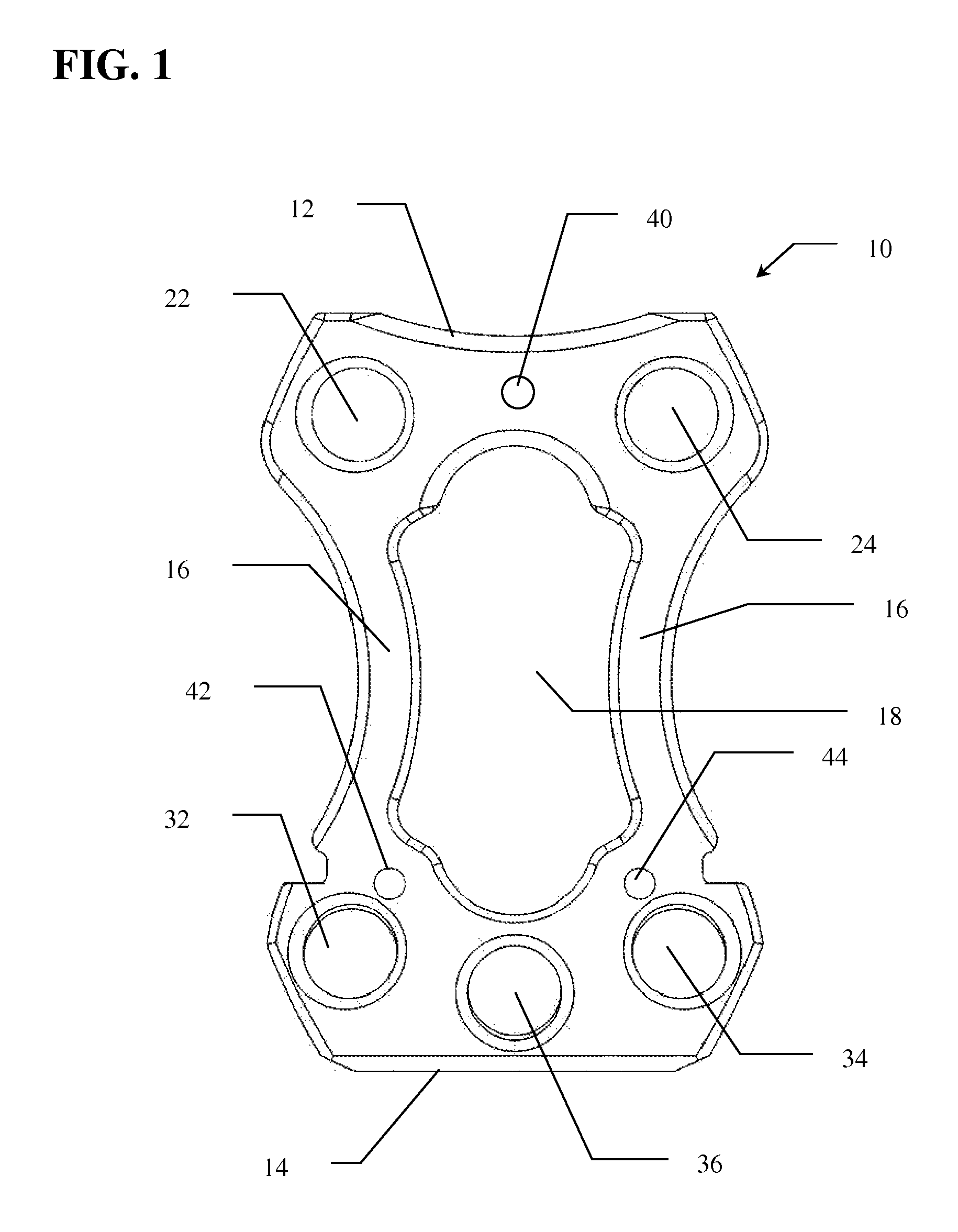
[0027]Referring to FIG. 1, the cervical stabilization plate (10) of the present invention is shown. In use, plate 10 is positioned between at least two vertebrae, above and below the disc to be treated and / or removed. In the preferred embodiment, plate 10 has a substantially hour-glass shaped frame having superior end 12 and inferior end 14 spaced at a predetermined distance by arms 16. Window 18 is defined by the open space between superior end 12, inferior end 14 and arms 16. Window 18 allows for direct visualization of the interface between the inferior aspect of the inter-body ca...


PUM


Abstract

An anti-subsidence, anti-translocation, fusion compression cervical plate system with interface visualization, drill guide and temporary pin is provided. In one embodiment the invention provides a vertebral plate for minimizing the ability of an inter-body cage, filled with bone (or BMP-soaked sponges, etc.), to telescope into the vertebral body and to minimize failure due to cages that telescope into adjacent vertebral bodies on a delayed basis after surgery, as well as creation of reverse lordosis due to such telescoping. Another embodiment provides method to reduce the gap between the inter-body cage and the vertebral body end plate intra-operatively using compression from the plate caused by an offset between the screw bores on the plate and the drill holes, as established with an asymmetric drill guide.

Description

CROSS REFERENCE TO RELATED APPLICATIONS[0001]This application is a non-provisional of U.S. Provisional Application 60 / 745,025, filed Apr. 18, 2006; which is incorporated herein by reference.FIELD OF THE INVENTION[0002]The invention relates to the field of surgery, more specifically to surgery of the cervical spine. It should be understood, however, that vertebrae other than the cervical vertebrae of the human spine may be retained with the disclosed apparatus and associated methods.BACKGROUND OF THE INVENTION[0003]Anterior cervical discectomy with fusion is an operation that involves relieving the pressure placed on nerve roots and the spinal cord by a herniated disc or bone spurs. This condition is referred to as nerve root compression. The procedure includes removing the damaged intervertebral disc, which is usually the source of the compression and placing a bone graft between vertebrae adjacent to the space left by the removed disc. The bone graft is commonly an inter-vertebral-...

Claims


Application Information

Patent Timeline
Patent Type & Authority Patents(United States)
IPC IPC(8): A61B17/80
CPCA61B17/1728A61B17/1757A61B17/7059A61B17/8014A61B17/808
Inventor FREEMAN, THOMAS B.JOHNSON, WESLEY
Owner UNIV OF SOUTH FLORIDA
Why Eureka
Try Eureka