Automotive muffler

a muffler and auto-type technology, applied in the field of mufflers, can solve the problems of plane stiffness, undesired acoustic emission of the muffler, plane stiffness, etc., and achieve the effect of increasing the stiffness of the shell

Active Publication Date: 2015-01-08
HONDA MOTOR CO LTD
View PDF15 Cites 17 Cited by
  • Summary
  • Abstract
  • Description
  • Claims
  • Application Information

AI Technical Summary

Benefits of technology

[0021]By placing the upper and lower flanges in a pre-stressed condition, the flanges are caused to be urged against the opposing walls of the corresponding shell halves so that the two parts are welded in a favorable manner. Alternatively or additionally, each flange may be welded to an opposing wall of the corresponding shell half while being placed in close contact with the opposing wall of the corresponding shell half. In particular, the flanges that are firmly connected to the upper and lower shell halves significantly contribute to the increased stiffness of the shell.
[0022]To provide a surface comple

Problems solved by technology

However, in modern motor vehicles, the floor panel is generally planar in shape, and allows a relatively limited space thereunder.
Low profile mufflers are advantageous for use in modern vehicle body designs, but have the disadvantage of lacking in plane stiffness.
A lack in plane stiffness means an increase in an undesired acoustic emission from the muffler owing to the vibrations of the shell wall of the muffler.
According to this prior art, each shell half is provided with a relatively large depth so that the side wall may not have an adequate stiffness, and may cause an undesired

Method used


Image

  • Automotive muffler
  • Automotive muffler
  • Automotive muffler

Examples


Embodiment Construction

)

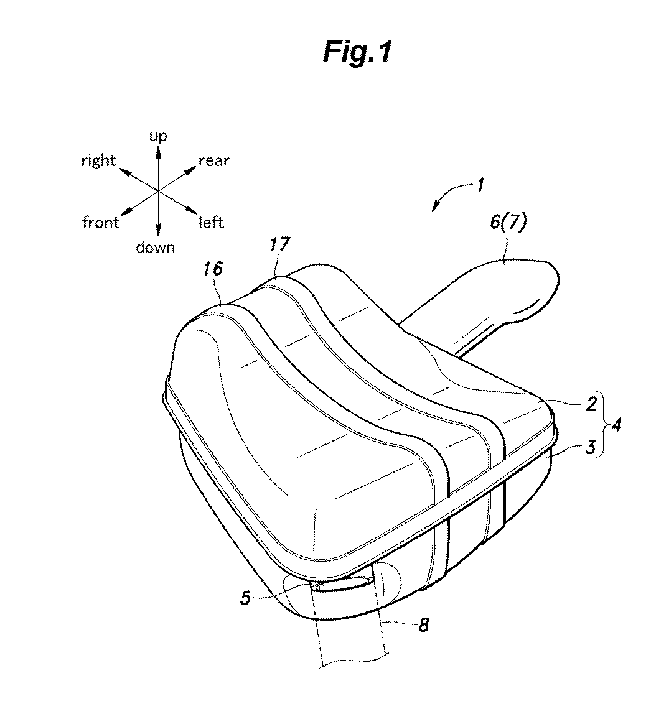
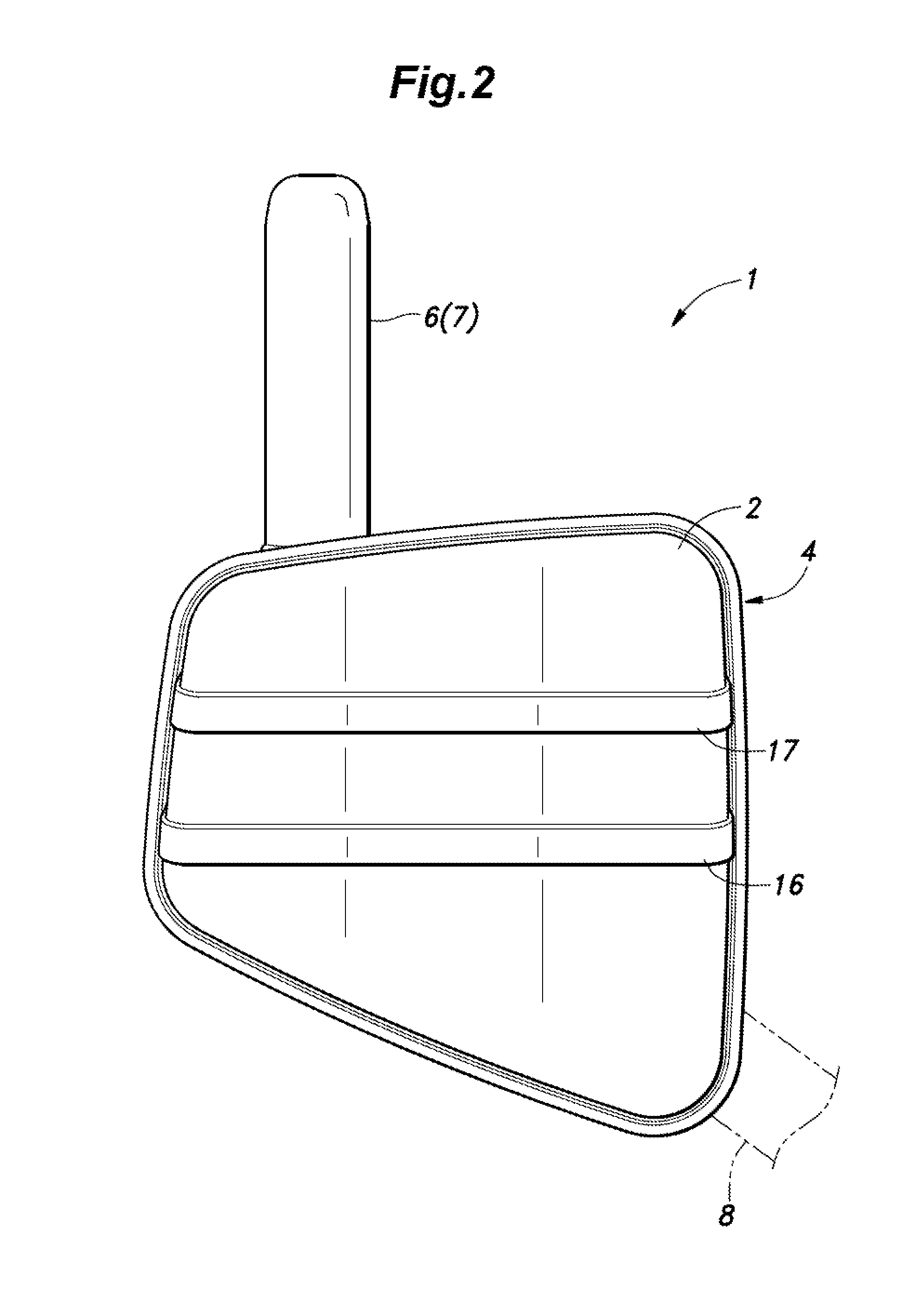
[0045]An automotive muffler 1 embodying the present invention is described in the following with reference to the appended drawings. In some of the drawings, various directions are indicated in an upper left corner for the convenience of description.

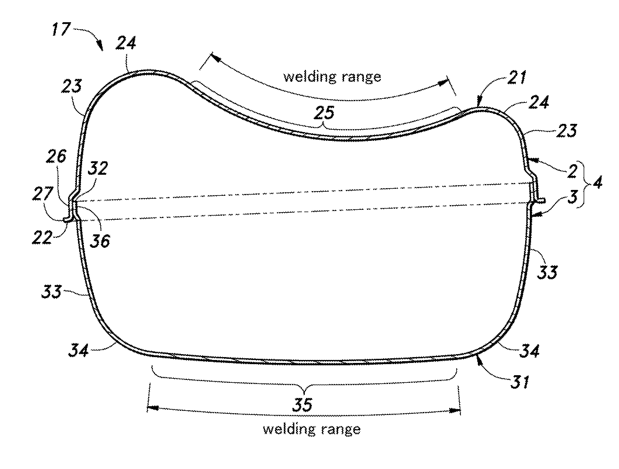
[0046]Referring to FIGS. 1 to 3, the muffler 1 comprises a shell 4 consisting of an upper shell half 2 and a lower shell half 3 each formed by stamping steel plate and being joined with each other, an inlet pipe 5 extending obliquely forward from a front left end of the lower shell half 3, and an outlet pipe 7 extending rearward from a rear right end of the lower shell half 3. The rear end of the outlet pipe 7 is formed as a tail pipe 6. As the tail pipe 6 can be considered as a part of the outlet pipe 7 for practical purposes, the tail pipe 6 is treated as a part of the outlet pipe 7 in the following description whenever appropriate. The muffler 1 is resiliently suspended from the lower surface of the vehicle body of a four-wheel passe...


PUM

PropertyMeasurementUnit
Angleaaaaaaaaaa
Lengthaaaaaaaaaa
Widthaaaaaaaaaa

Abstract

In a muffler comprising a shell formed by joining a pair of shell halves each including a bottom wall and a side wall and defining an opening opposite to the bottom wall, the shell halves being joined to each other at the openings thereof, the muffler further comprising an inlet pipe for introducing exhaust gas into the shell and an outlet pipe for expelling exhaust gas from inside the shell, a depth of one of the shell halves is greater than a depth of the other shell half, and the inlet pipe and the outlet pipe are connected to the side wall of the one shell half so that the overall plane stiffness of the shell is well balanced and maximized. Therefore, without adding any reinforcement or increasing the wall thickness of the shell, the acoustic emission from the muffler can be minimized.

Description

TECHNICAL FIELD [0001]The present invention relates to a muffler forming a part of an exhaust system of an internal combustion engine of a motor vehicle.PRIOR ART [0002]A motor vehicle powered by an internal combustion engine is provided with an exhaust system which includes an exhaust manifold, a catalyst device, an exhaust pipe and a muffler for the purposes of removing noxious substances from the exhaust gas and reducing exhaust noises. The muffler typically consists of a shell made of steel plate, a plurality of separators that separate the interior of the shell into a number compartments (such as an expansion chamber and a resonance chamber), an inlet pipe for introducing exhaust gas into the shell and an outlet pipe extending rearward from the shell to expel the exhaust gas. These components are usually joined together by welding such as laser welding. See JP2004-245052A, for instance. The expansion chamber attenuates the pulsating pressure changes of the exhaust gas, and the ...

Claims


Application Information

Patent Timeline
IPC IPC(8): F01N13/08F01N13/18
CPCF01N13/1888F01N13/08F01N1/083F01N1/084Y10T29/49398
Inventor HAMASHIMA, HIDENORIWATANABE, SATOSHISUZUKI, HIDENORI
Owner HONDA MOTOR CO LTD
Why Eureka
Try Eureka