Variable magnification projection optical system and projection display apparatus

Active Publication Date: 2015-03-12
FUJIFILM CORP
View PDF1 Cites 6 Cited by
  • Summary
  • Abstract
  • Description
  • Claims
  • Application Information

AI Technical Summary

Benefits of technology

[0034]The variable magnification projection optical system according to the present invention takes a simple two group configuration in which two groups are both positive lens groups and the reduction side is telecentric. This allows reduction in size, weight, and cost, and the telecentricity on the reduction side is maintained while securing aback focus that allows the insertion of a prism or the like although the overall length of the l

Problems solved by technology

The projection lens described in aforementioned Japanese Unexamined Patent Publication No. 2010-113150, however, is not of a telecentric configuration on the reduction side and cannot be used in projection display devices that require, for example, a color combining prism or a TIR prism, although it has a two group simple and compact configuration.
Further, the configuration well known as two group zoom in which a negative first lens group and a positive second lens group are disposed in order from the magnification side, as in Japanese Unexamined Patent Publication No. 2010-113150, may secure a relatively a long back focus, but the second lens group whi

Method used


Image

  • Variable magnification projection optical system and projection display apparatus
  • Variable magnification projection optical system and projection display apparatus
  • Variable magnification projection optical system and projection display apparatus

Examples


example 1

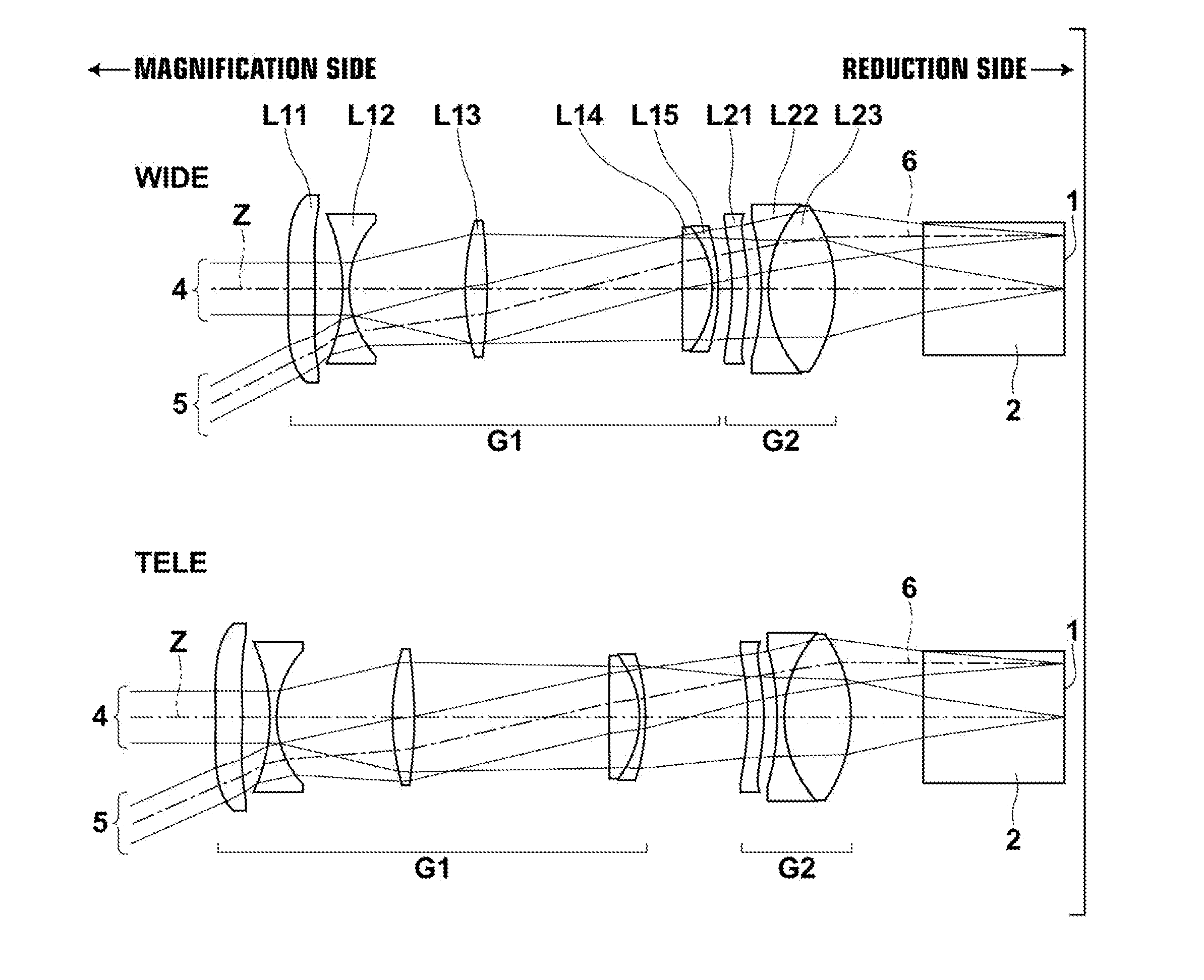
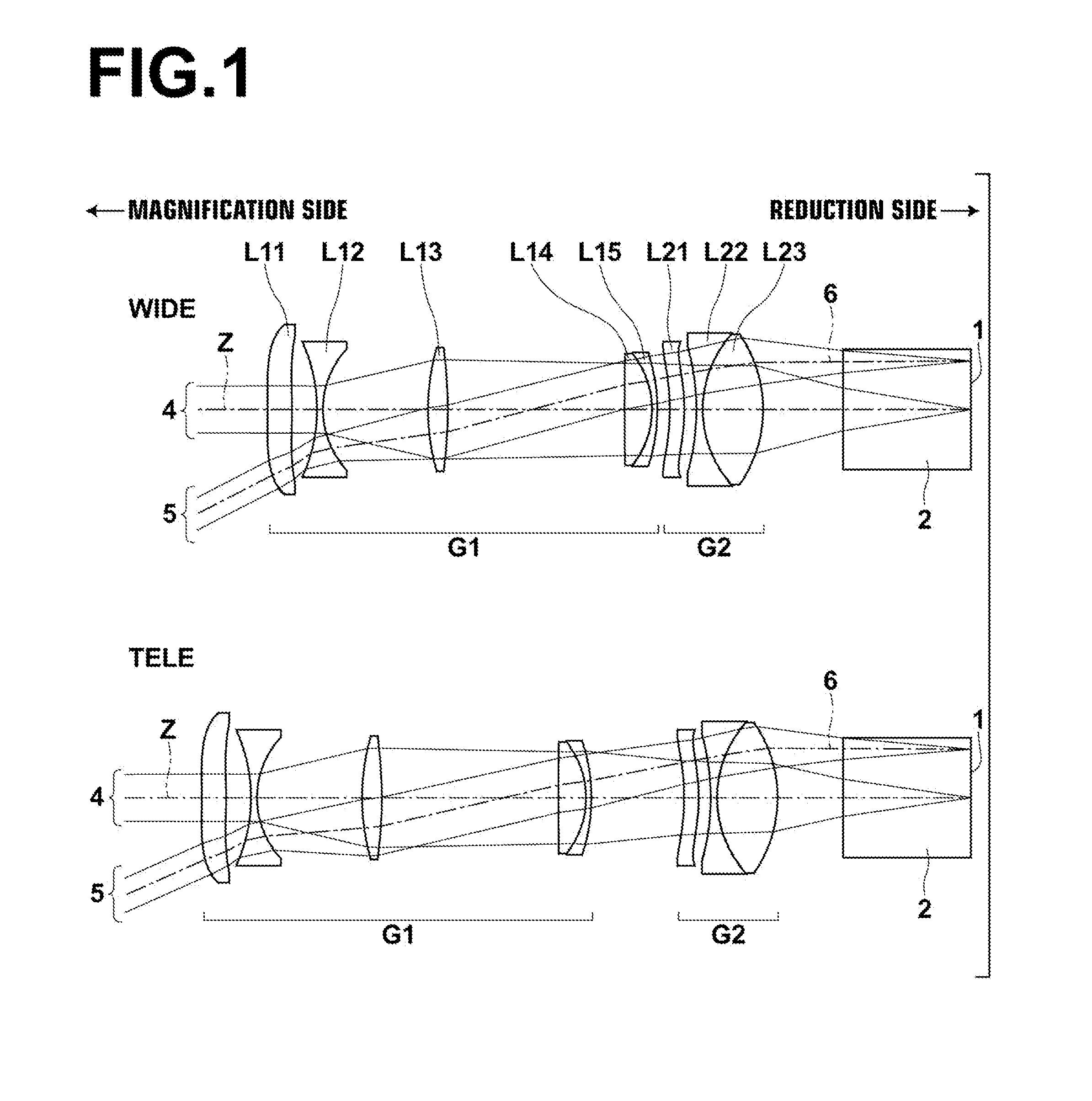
[0086]FIG. 1 illustrates the lens configuration of a variable magnification projection optical system of Example 1. In FIG. 1, the upper side diagram with a sign “WIDE” attached thereto illustrates the lens configuration of each lens group at the wide angle end while the lower side diagram with a sign “TELE” attached thereto illustrates the lens configuration of each lens group at the telephoto end.

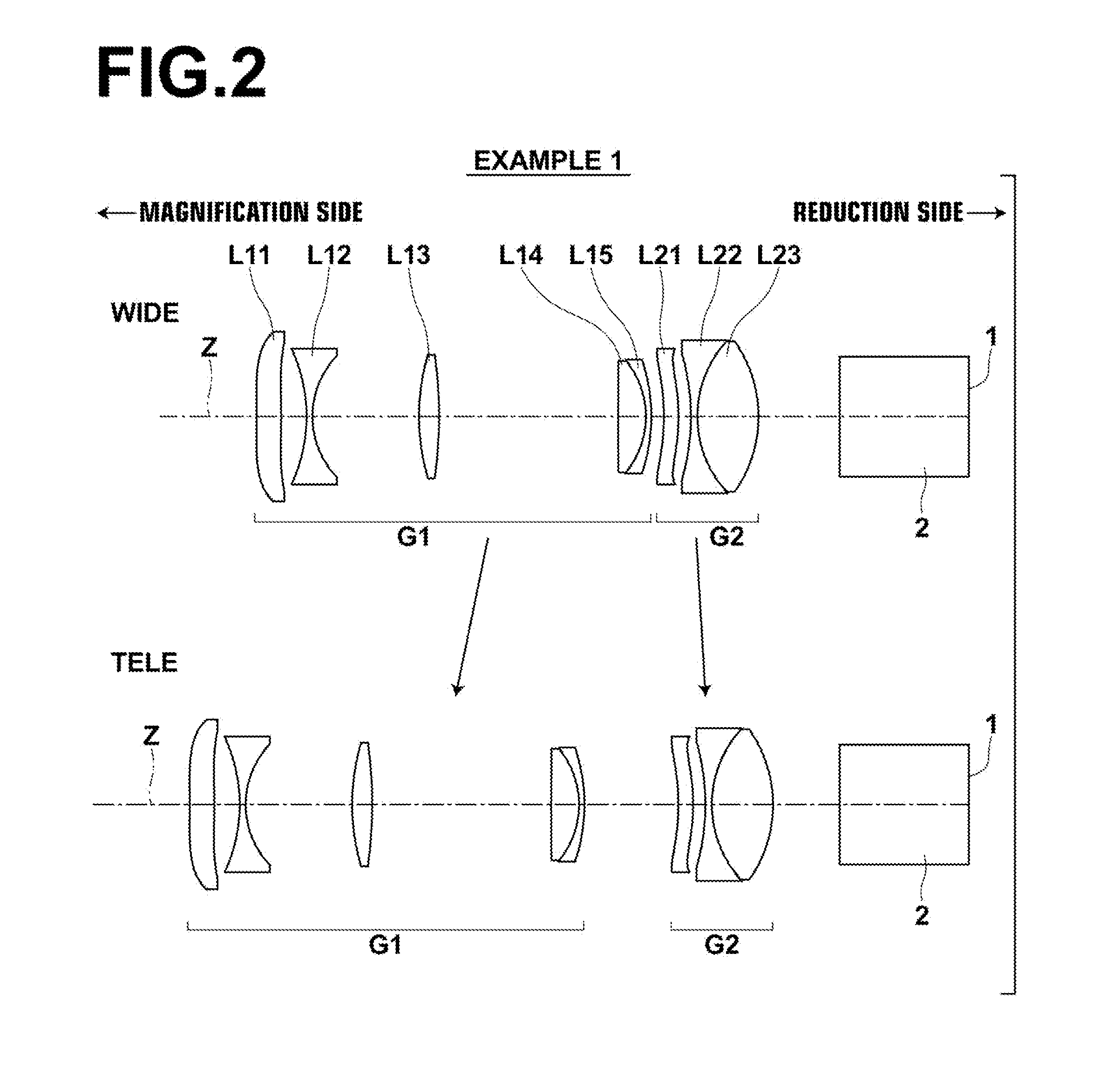
[0087]The variable magnification projection optical system of Example 1 is of a two group configuration in which a first lens group G1 having a positive refractive power and a second lens group G2 having a positive refractive power are disposed in order from the magnification side, and the reduction side is made telecentric. The first lens group G1 is moved to the magnification side and the second lens group G2 is moved to the reduction side during the magnification change from the wide angle end to the telephoto end. FIG. 2 schematically illustrates the movement directions of the two len...

example 2

[0104]FIG. 3 illustrates the lens configuration of a variable magnification projection optical system of Example 2. The variable magnification projection optical system of Example 2 has an almost identical configuration to that of Example 1, but differs in that the lens L14 is a positive meniscus lens with a convex shape on the reduction side. Note that the variable magnification projection optical system of Example 2 is configured such that the focusing when the projection distance is changed is performed by moving the first lens group G1.

[0105]Tables 4, 5, and 6 respectively show basic lens data, variable surface distances, and aspherical surface coefficients of the variable magnification projection optical system of Example 2. A to L of FIG. 7 show each aberration diagram of the variable magnification projection optical system of Example 2.

TABLE 4Example 2 Basic Lens Data (Focal Lengths = 1.00 to 1.10 to 1.15)SiRiDiNdjνdj 1*−11.5620.2791.491057.58 2*−6.9160.2503−1.7730.0631.53174...

example 3

[0106]FIG. 4 illustrates the lens configuration of a variable magnification projection optical system of Example 3. The variable magnification projection optical system of Example 3 has an almost identical configuration to that of Example 1, but differs in that the lens L11 has a biconcave shape in the paraxial region, the lens L14 is a negative meniscus lens with a convex surface on the magnification side, the lens L15 is a biconvex lens, and the lens L14 and the lens L15 are not cemented. Note that the variable magnification projection optical system of Example 3 is configured such that the focusing when the projection distance is changed is performed by moving the second lens group G2.

[0107]Tables 7, 8, and 9 respectively show basic lens data, variable surface distances, and aspherical surface coefficients of the variable magnification projection optical system of Example 3. A to L of FIG. 8 show each aberration diagram of the variable magnification projection optical system of E...


PUM


Abstract

A variable magnification projection optical system substantially consisting of two lens groups of a first lens group having a positive refractive power and is moved during magnification change, and a second lens group having a positive refractive power and is moved during magnification change, in which the variable magnification projection optical system is configured such that the reduction side is telecentric.

Description

CROSS-REFERENCE TO RELATED APPLICATIONS[0001]This application is a Continuation of PCT International Application No. PCT / JP2013 / 002916 filed on May 2, 2013, which claims priority under 35 U.S.C. §119 (a) to Japanese Patent Application No. 2012-112084 filed on May 16, 2012. Each of the above applications is hereby expressly incorporated by reference, in its entirety, into the present application.BACKGROUND OF THE INVENTION[0002]1. Technical Field[0003]The present invention relates to a variable magnification projection optical system and a projection display apparatus, and more specifically to a two-group variable magnification projection optical system suitable for magnifying and projecting a light beam having image information from, for example, a light valve onto a screen, and a projection display apparatus equipped with the same.[0004]2. Background Art[0005]Recently, projection display devices that use light valves, such as liquid crystal display devices and DMD (Digital Micro-Mi...

Claims


Application Information

Patent Timeline
IPC IPC(8): G02B13/22G02B15/14
CPCG02B15/14G02B13/22G02B13/18G02B15/1421G03B21/14
Inventor AMANO, MASARU
Owner FUJIFILM CORP
Why Eureka
Try Eureka