Fluid Quality Sensing Means with Reference Sensor

a technology of reference sensor and fluid, which is applied in the direction of mechanical equipment, instruments, material impedance, etc., can solve the problems of engine damage, engine oil acidic, increased engine down time and operation cost,

Active Publication Date: 2015-03-19
QI BAOHUA
View PDF12 Cites 15 Cited by
  • Summary
  • Abstract
  • Description
  • Claims
  • Application Information

AI Technical Summary

Benefits of technology

[0015]The present invention provides apparatus for detecting changes in fluid quality using signals obtained from a fluid quality sensor for exposure to a ...

Problems solved by technology

In addition, some oil additives, such as viscosity improvers and anti-oxidants breaks down during engine operation, especially at high temperature and in the presence of water and metallic particles, making the engine oil more acidic.
However, too frequent replacement of the engine oil increases the down time and operation cost of the engine, while if the engine oil exceeds its useful life, the engine could be damaged.
For example, when an oil filter lost its capability in removing debris in the engine oil, the concentration of contaminants would rise rapidly, causing a sudden change in the sensing values obtained from the oil quality sensors.
Thereby by using changing rate the sensing values, oil filter failures can be detected.
However, in examining fluid quality, it is difficult to determine a reference value to compare with due to the sensitivity to fluid types.
The effect of fluid temperature can be compensated by using a temperature sensor, while that of fluid type is difficult to compensate, since the sensing for fluid type itself needs a quality sensor, and fluid quality changes with time.
However, in practice, normally it is difficult to measure all available fluids, since in addition to large number of fluid types, a new fluid can be easily ...

Method used


Image

  • Fluid Quality Sensing Means with Reference Sensor
  • Fluid Quality Sensing Means with Reference Sensor
  • Fluid Quality Sensing Means with Reference Sensor

Examples


Embodiment Construction

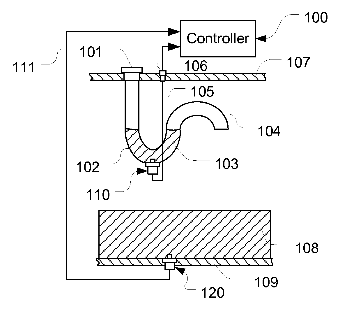
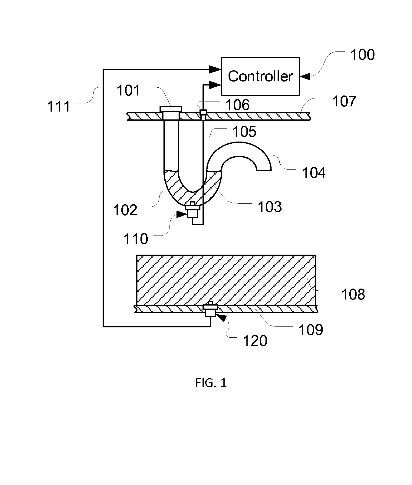
[0030]Referring to FIG. 1, a fluid quality sensor 120 is mounted on a bottom wall 109 of a fluid tank (not shown) contacting a fluid 108. On a top wall 107 of the fluid tank, a cap 101 is positioned on the inlet of an “S” shape tube with a “U” shape trap section 102 and an outlet section 104. On the bottom of the trap section 102, a reference fluid quality sensor 110 is mounted, contacting trapped fluid 103 in the trap section 102. The fluid quality sensor 120 is electrically connected to a controller 100 with signal lines 111, while the reference fluid quality sensor 110 is electrically connected to the controller 100 with signal lines 105 via a port 106 on the top wall 107.

[0031]When a fluid is refilled into the fluid tank, new fluid is trapped in the trap section 102. The trapped fluid is isolated from rest of the fluid, therefore, its quality doesn't change with fluid usage. The fluid quality of the trapped fluid in the trap section 102 and that of the aged fluid in the fluid ta...


PUM


Abstract

A sensing apparatus for detecting fluid quality change using signals obtained from a fluid quality sensor for exposure to a fluid and a reference sensor positioned in a reference sensing means having a fluid trap section holding a part of the fluid. Sensing values obtained from the fluid quality sensor and the reference sensor are compared in determining an aging factor. An application of the sensing apparatus is an apparatus for detecting engine oil quality change in an engine system. With the sensing apparatus, a first aging factor can be calculated after an engine cold soak and a second one can be obtained during engine operation. With these two aging factors, in addition to oil quality change, failures in the engine system and sensors, and oil change events can also be detected. Additionally, since reference sensing values are provided by the reference sensor, power disconnections have least effects.

Description

[0001]This present application claims priority from U.S. provisional application No. 61 / 701,494 having the same title as the present invention and filed on Sep. 14, 2012.FIELD OF THE INVENTION [0002]This invention relates to a method and apparatus for electrical measurement of a quality of a fluid in a fluid system, and more particularly to a method and apparatus using impedance of a fluid to detect changes in fluid quality and issues in a fluid system.BACKGROUND OF THE INVENTION[0003]In a fluid system, to have an adequate fluid replacement maintenance schedule for minimizing maintenance costs and system downtime, and to detect changes in fluid properties and issues in the fluid system, fluid quality needs to be monitored. One example of such a fluid system is an internal combustion engine system, in which engine oil is used for dissipating heat generated by friction of mechanical components and lubricating the movement of the mechanical components. During engine operations, soot pa...

Claims


Application Information

Patent Timeline
Owner QI BAOHUA
Why Eureka
Try Eureka