Load and torque sensing systems utilizing magnetic key for mechanical engagement

a technology of magnetic key and mechanical engagement, applied in the direction of gearing, hoisting equipment, instruments, etc., can solve the problems of fragile components and/or high cost, and achieve the effect of facilitating the assembly and disassembly of load and torque bearing and/or transmitting assemblies

Active Publication Date: 2015-05-21
FUTEK ADVANCED SENSOR TECH
View PDF7 Cites 12 Cited by
  • Summary
  • Abstract
  • Description
  • Claims
  • Application Information

AI Technical Summary

Benefits of technology

[0003]The present invention facilitates the assembly and disassembly of load and torque bearing and/or transmitting assemblies by eliminating the need for wedge-fit or friction fit keys, Cotter pins and other components that must be forcibly driven into place and/or deformed to stay in place. In general, this is accomplished by providing a locking element that is held in

Problems solved by technology

In either case, disassembly of the system typically requires the use of tools and often requires replacement of the locking component, particularly if the system is reassembled numerous times. This disadvantag

Method used


Image

  • Load and torque sensing systems utilizing magnetic key for mechanical engagement
  • Load and torque sensing systems utilizing magnetic key for mechanical engagement
  • Load and torque sensing systems utilizing magnetic key for mechanical engagement

Examples


Embodiment Construction

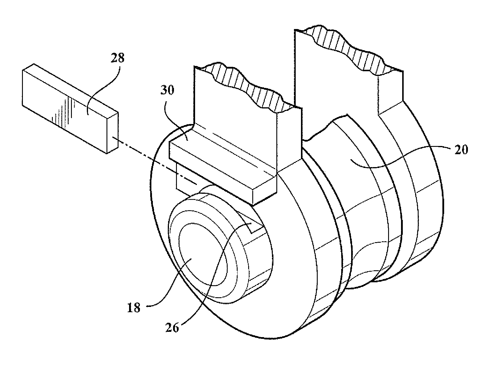
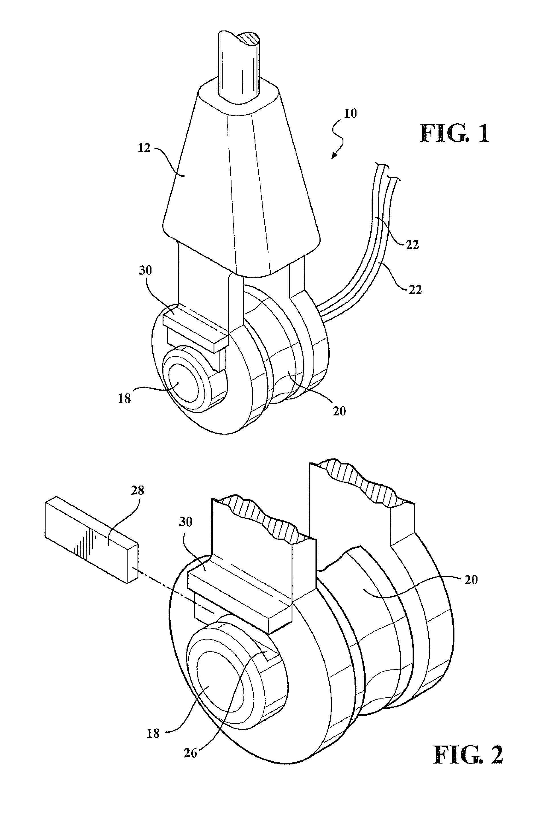
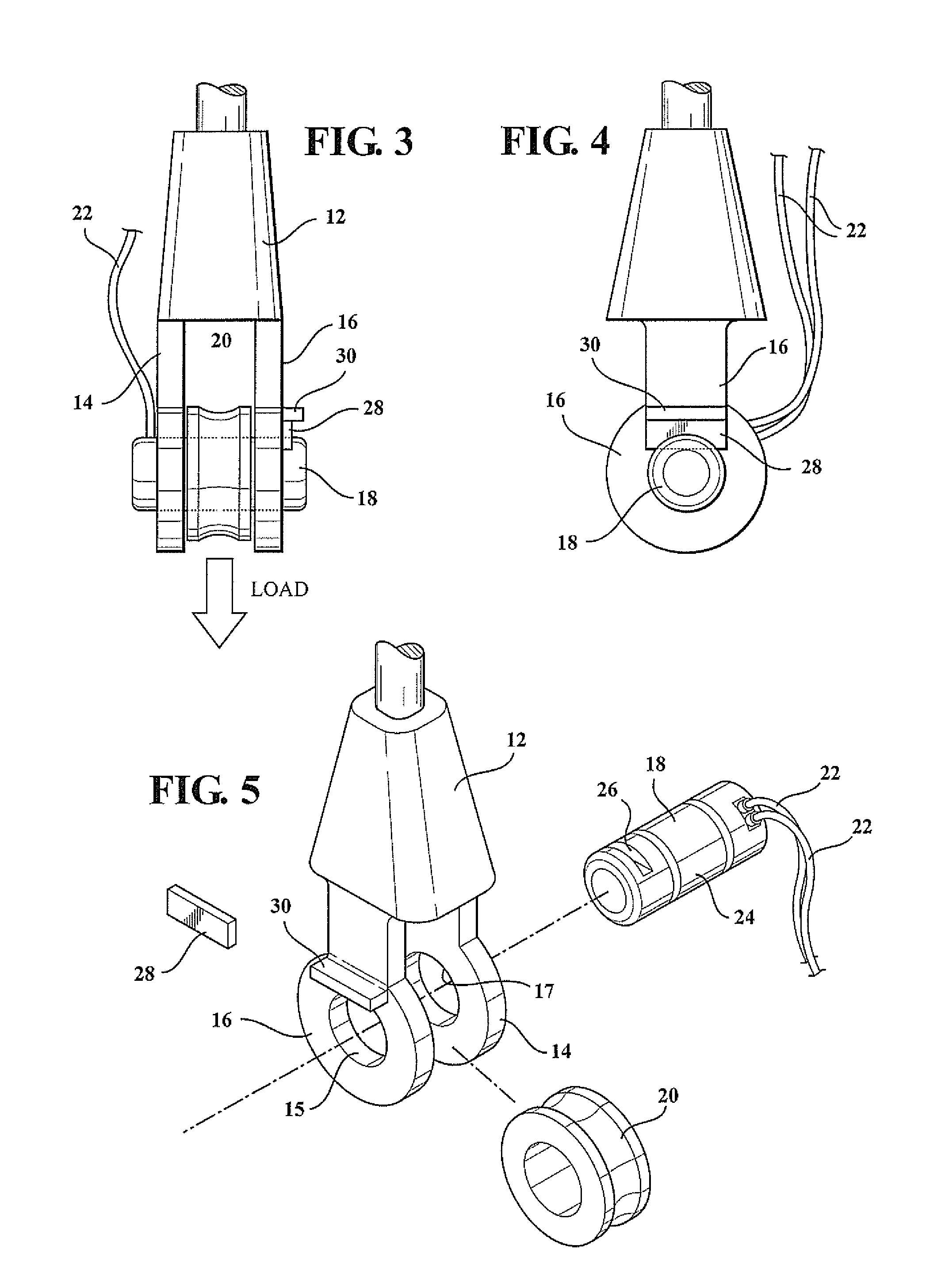
[0018]Referring to FIGS. 1-5, there is shown a clevis structure 10, sometimes called a “shackle”, of the type typically used as a pulley to carry a vertical load. It can also be used to anchor a rod or cable. The structure 10 comprises the clevis body 12 having spaced apart, parallel legs 14, 16, the larger lower circular portions of which are drilled out to exhibit holes 15, 17 that are coaxial and equal in diameter. An instrumented clevis pin 18 slides into and through the holes 15, 17 and is axially long enough to extend beyond the outsides of both of the clevis legs 14, 16 as best shown in FIG. 3. The clevis pin 18 is instrumented as a load cell of a known type, which cell generates electrical signals representing vertical load as a function of bending in the pin 18. These signals are connected by wires 22 to a recording and / or analytical system, such as a computer (not shown). A pulley 20 is mounted on the smooth center portion 24 of the clevis pin 18 for rotation relative ther...


PUM


Abstract

Two forms of load bearing or transmitting structures are disclosed wherein each uses magnetism to hold a key in one of two bodies to prevent movement therebetween. One embodiment is a clevis, wherein the clevis pin is instrumented as a load cell and a magnetic key resides in a slot in a portion of the clevis pin which protrudes outside of one of the clevis legs. In another embodiment, torque is transmitted between a shaft and a coupling by means of keys that are held in keyways by magnetism thereby to provide a torque coupling between the shaft and coupling members.

Description

FIELD OF THE INVENTION[0001]The invention relates to mechanical assemblies for force and torque-sensing applications and more particularly to the use of a magnetic linking component such as a key to couple or connect two components of such an assembly.BACKGROUND OF THE INVENTION[0002]There are numerous mechanical assemblies for bearing or transmitting forces where it is necessary to establish and maintain a physical relationship between two associated components by means of a third “locking” component such as a key or pin. As one example, a clevis pin is often held in place between the two legs of a clevis by means of a Cotter pin. The Cotter pin prevents the clevis pin from moving relative to the clevis or shackle. As another example, a shaft may be coupled to another shaft or a collar by means of a key or set of keys. Here, the key prevents relative rotational movement of the two components it “locks” together. In both of these examples, the third component; i.e., the Cotter pin o...

Claims


Application Information

Patent Timeline
IPC IPC(8): F16D1/08G01L3/14F16H55/36
CPCF16D1/08G01L3/14F16H55/36F16D1/04F16D1/0876Y10T403/7018
Inventor MOKHBERY, JAVADMEHRAN, AMIRREZABARRETT, GARY
Owner FUTEK ADVANCED SENSOR TECH
Why Eureka
Try Eureka