Integrated Switch and Limiter Circuit

a limiter circuit and integrated switch technology, applied in the field of electronic circuitry, can solve the problem of limiting the signal on the signal line from fully propagating from the source to the receiver, and achieve the effect of reducing the risk of interferen

Active Publication Date: 2015-06-11
PSEMI CORP
View PDF7 Cites 17 Cited by
  • Summary
  • Abstract
  • Description
  • Claims
  • Application Information

AI Technical Summary

Benefits of technology

[0029]FIG. 5A is a circuit diagram of a prior art limiter comprising a power / amplitude detector electrically coupled to the gate node of a field effect transistor in a shunt configuration.
[0030]FIG. 5B is a circuit diagram of a prior art limiter comprising a power / amplitude detector electrically coupled to the gate node of a field effect transistor in a switched signal configuration.

Problems solved by technology

However, if the voltage at the control input has a value corresponding to the “controlled impedance” state of LE, the signal line is partially shunted through LE to circuit ground, essentially limiting the signal on signal line from fully propagating from the source to the receiver.

Method used


Image

  • Integrated Switch and Limiter Circuit
  • Integrated Switch and Limiter Circuit
  • Integrated Switch and Limiter Circuit

Examples


Embodiment Construction

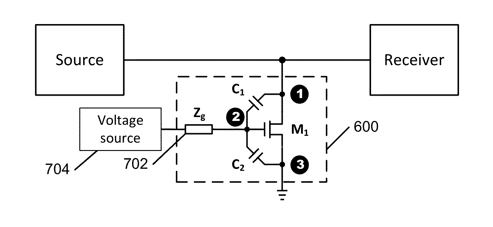
[0073]FIG. 6A is a circuit diagram of a generalized embodiment of the invention. A self-activating, adjustable threshold limiter 600 in accordance with the present invention includes a limiting element LE. A first coupling element CE1 is electrically connected from a signal node 1 of LE to a control input 2 of LE. A second coupling element CE2 is electrically connected from the control input 2 of LE to a second signal node 3 of LE (nominally an output node). An initial bias (control) voltage Vctrl is also supplied to the control input 2 of LE to set the limiting threshold for the limiter 600.

[0074]The limiting element LE is preferably a voltage controlled element that shows a high degree of isolation between input and output, has an essentially non-conducting (“off”) state if the voltage at the control input 2 is less than a set value, has a “variable impedance” or “controlled impedance” state in which it behaves as a voltage controlled current source in response to application of a...


PUM

PropertyMeasurementUnit
voltage amplitudeaaaaaaaaaa
resistanceaaaaaaaaaa

Abstract

A fast response time, self-activating, adjustable threshold limiter including a limiting element LE, a first coupling element CE1 electrically connected from a signal node of LE to a control input of LE, and a second coupling element CE2 electrically connected from the control input of LE to a nominal node of LE. An initial bias (control) voltage is also supplied to the control input of LE to dynamically control the limiting threshold for the limiter. Embodiments include usage of self-activating adjustable power limiters in combination with series switch components in a switch circuit in lieu of conventional shunt switches.

Description

CROSS-REFERENCE TO RELATED APPLICATIONS[0001]The present application is a Continuation-In-Part (CIP) of, and claims priority to, co-pending and commonly assigned U.S. patent application Ser. No. 13 / 841,490, entitled “Self-Activating Adjustable Power Limiter”, filed on Mar. 15, 2013, the entire disclosure of which is incorporated herein by reference.BACKGROUND[0002](1) Technical Field[0003]This invention relates to electronic circuitry, and more particularly to a self-activating adjustable threshold power limiter circuit.[0004](2) Background[0005]Limiter circuits are used in electronic systems to limit power, voltage, or current to protect electrically connected “downstream” electronic devices from being damaged by excessive power, voltage, or current from a source, which may be an “upstream” power source, signal source, antenna, device being tested, etc. For example, FIG. 1 is a block diagram of a prior art limiter 100 electrically connected to limit the power Ps from a source 102 d...

Claims


Application Information

Patent Timeline
Patent Type & Authority Applications(United States)
IPC IPC(8): H03K5/08H03K17/687
CPCH03K17/687H03K5/08H03K5/082H01L27/0288H03G7/004H03G7/06H03G11/00H03J2200/10H03K17/302Y10T29/49105
Inventor LU, JIANHUABACON, PETERYANDURU, NAVEENCOMFOLTEY, EDWARD NICHOLASCONRY, MICHAELYANG, CHIEH-KAI
Owner PSEMI CORP
Why Eureka
Try Eureka