Method for Controlling an Elastic Extensible Screen Having a Variable Degree of Opening and Suitable Control Device

a technology of elastic extensibility and control device, which is applied in the direction of curtain suspension device, building components, sustainable buildings, etc., can solve the problems of manual adjustment difficulties

Active Publication Date: 2015-07-09
SOMFY ACTIVITES SA
View PDF32 Cites 16 Cited by
  • Summary
  • Abstract
  • Description
  • Claims
  • Application Information

AI Technical Summary

Benefits of technology

[0019]An approach may be used such that during the prior deployment step, the screen has a maximum deformation, or a predetermined deformation sufficient to significantly increase its aperture ratio relative to the minimum value without deformation. In so doing, it is possible to limit the contrast introduced by the deployment of the screen.
[0020]Alternatively, an approach may be adopted such that during the prior deployment step, the screen is not subjected to a noteworthy traction force, such that it has a null or minimal deformation. This option offers the advantage of simplicity of implementation.
[0024]According to one embodiment, the device comprises a winding tube to wind and unwind the screen between a wound position and a deployed position, the motorized mechanism being a mechanism for driving the winding tube, driven by a rotating actuator that can in particular be a direct current electric motor or a brushless motor, offering the advantage of precise driving at low speeds.
[0025]According to one embodiment, the device further comprises a load bar positioned at one free end of the screen. The load bar can have a mass such that, suspended from the free end of the screen, it causes a predetermined traction force sufficient to cause, during deployment, a noteworthy deformation of the screen and a substantial increase of the aperture ratio above the minimum value. The device can comprise a support stop for stopping the load bar in the deployed position of the screen, which prohibits the movement of the load bar beyond the deployed position and makes it possible to modulate the traction force in the deployed position.

Problems solved by technology

Using a motorized mechanism does away with the difficulties encountered with manual adjustment.

Method used


Image

  • Method for Controlling an Elastic Extensible Screen Having a Variable Degree of Opening and Suitable Control Device
  • Method for Controlling an Elastic Extensible Screen Having a Variable Degree of Opening and Suitable Control Device
  • Method for Controlling an Elastic Extensible Screen Having a Variable Degree of Opening and Suitable Control Device

Examples


first embodiment

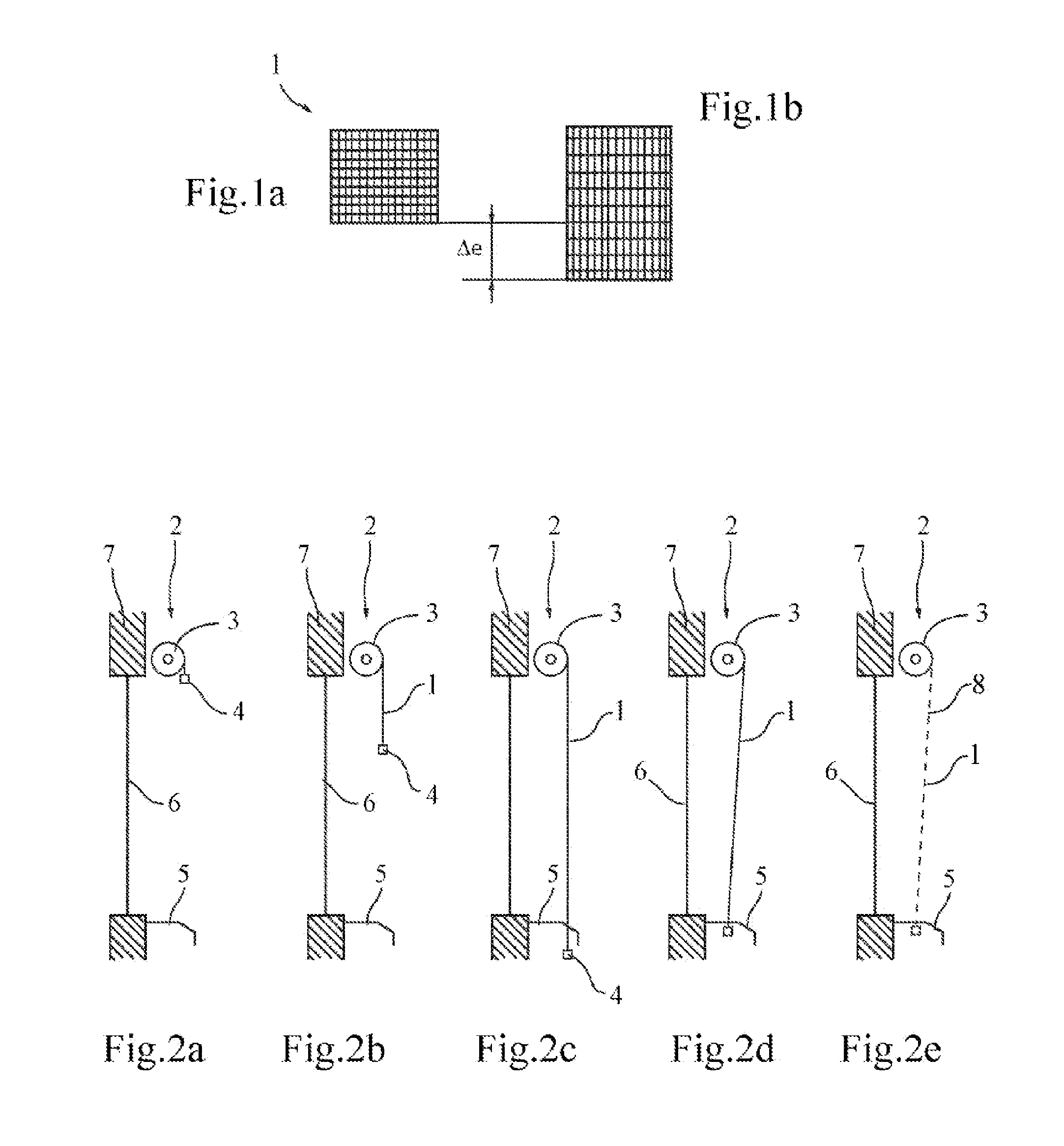
[0044]FIGS. 2a to 2e show a device 2 for controlling the permeability of a screen 1 of the preceding type, according to a The screen 1 is initially wound on a winding tube 3 driven by a motor, preferably housed in the winding tube 3. A load bar 4 is arranged at one free end of the screen. The device is arranged across from an opening, in the case at hand a glass opening 6, in a wall 7 of a building, the glass 6 and the wall 7 separating a zone to be protected, where the device is located, from an outer zone. The zone to be protected can for example be a room located inside a building. The outer zone may be another room or a zone situated outside the building. The two zones can also be situated in the same room. The device is completed by a bolt 5, arranged at the threshold of the glass opening 6. Said bolt 5 cooperates with one end of the load bar 4 that protrudes past the lateral rim of the screen 1.

[0045]During its deployment, illustrated in FIGS. 2b and 2c, the screen has a mini...

second embodiment

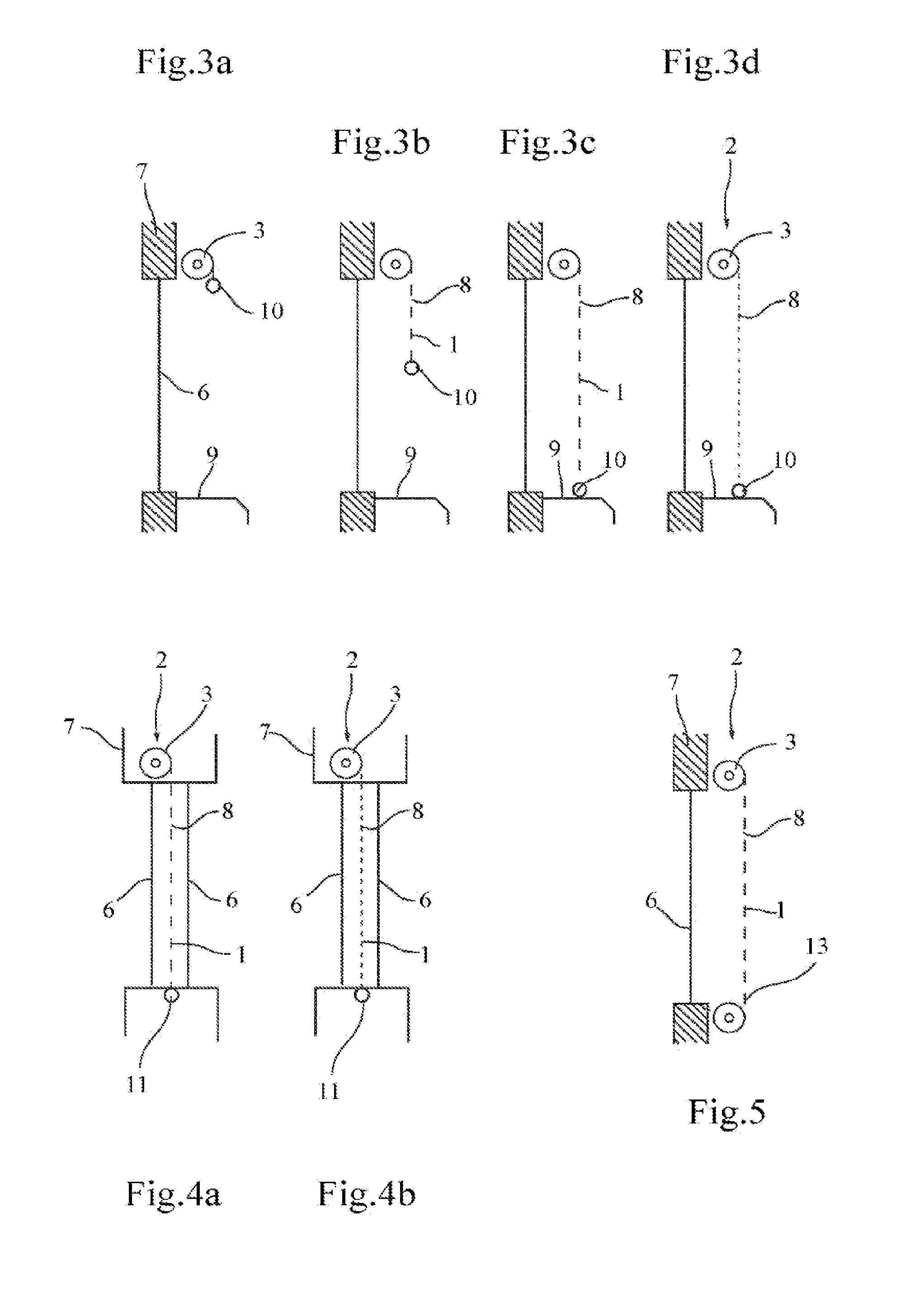
[0047]FIGS. 3a to 3d show a device according to the invention, which differs from the previous embodiment in that the load bar has a sufficient mass to cause a significant predetermined deformation of the screen. During its deployment, in FIGS. 3b and 3c, the screen therefore offers a high aperture ratio, preferably greater than 10%, for example approximately 15 to 20%. At the end of deployment, the load bar rests on a support 9 making up an end-of-travel stop. By continuing to drive the winding tube with the motor in the unwinding direction, the traction exerted on the screen is gradually decreased, until a minimum aperture ratio is obtained that is preferably below 5%, or even close to 0%, as illustrated in FIG. 3d.

[0048]This embodiment offers the advantage, relative to the previous version, of making it possible to continuously increase the darkening of the zone to be protected from the wound position of FIG. 3a to the position with a minimum aperture ratio in FIG. 3d. Thus, the...


PUM


Abstract

In order to control the light or air permeability of an elastic extensible screen (1) disposed between an area to be protected and an external area, and having a permeability that varies with a pulling force exerted on the screen, a motorized mechanism (3) adjusts the pulling force on the screen in response to a setpoint signal, which can be determined on the basis of one or a plurality of signals from one or a plurality of sensors (12, 14, 15), in particular light sensors.

Description

TECHNICAL FIELD OF THE INVENTION[0001]The invention relates to the control of a screen. The term “screen” will be used here to refer generically to blinds, awnings, canvases, lining curtains or mosquito nets designed to be deployed and retracted, vertically, horizontally or obliquely, in particular to conceal openings in buildings or protect access to such openings, or to protect from outside sun or rain, or to form projection, partitioning or decorative screens. The invention more particularly relates to the control of an elastically extensible screen allowing more or less light and / or air to pass based on a traction to which it is subjected.BACKGROUND OF THE INVENTION[0002]Motorized screen devices are known making it possible to vary the quantity of light and energy entering through an opening. These are essentially Venetian screens, the orientation of the slats of which varies. It is, however, necessary to note that the incoming quantity follows laws that it is very difficult, if...

Claims


Application Information

Patent Timeline
Patent Type & Authority Applications(United States)
IPC IPC(8): E06B9/68E06B9/40
CPCE06B9/68E06B2009/6809E06B9/40E06B2009/6827Y02A30/24Y02B80/00
Inventor CAVAREC, PIERRE-EMMANUELLAGARDE, ERICNEUMAN, SERGE
Owner SOMFY ACTIVITES SA
Why Eureka
Try Eureka