Optical disc comprising a watermark and a method and recorder for recording such a disc

a technology of optical discs and watermarks, applied in the field of optical discs, can solve problems such as reflection changes

Inactive Publication Date: 2010-02-11
KONINKLIJKE PHILIPS ELECTRONICS NV
View PDF4 Cites 0 Cited by
  • Summary
  • Abstract
  • Description
  • Claims
  • Application Information

AI Technical Summary

Benefits of technology

[0055]FIG. 9 shows the effect of duplication without DC Contro

Problems solved by technology

Because the digital sum value modulation allows the choice of several different channel bits groups be

Method used


Image

  • Optical disc comprising a watermark and a method and recorder for recording such a disc
  • Optical disc comprising a watermark and a method and recorder for recording such a disc
  • Optical disc comprising a watermark and a method and recorder for recording such a disc

Examples


Embodiment Construction

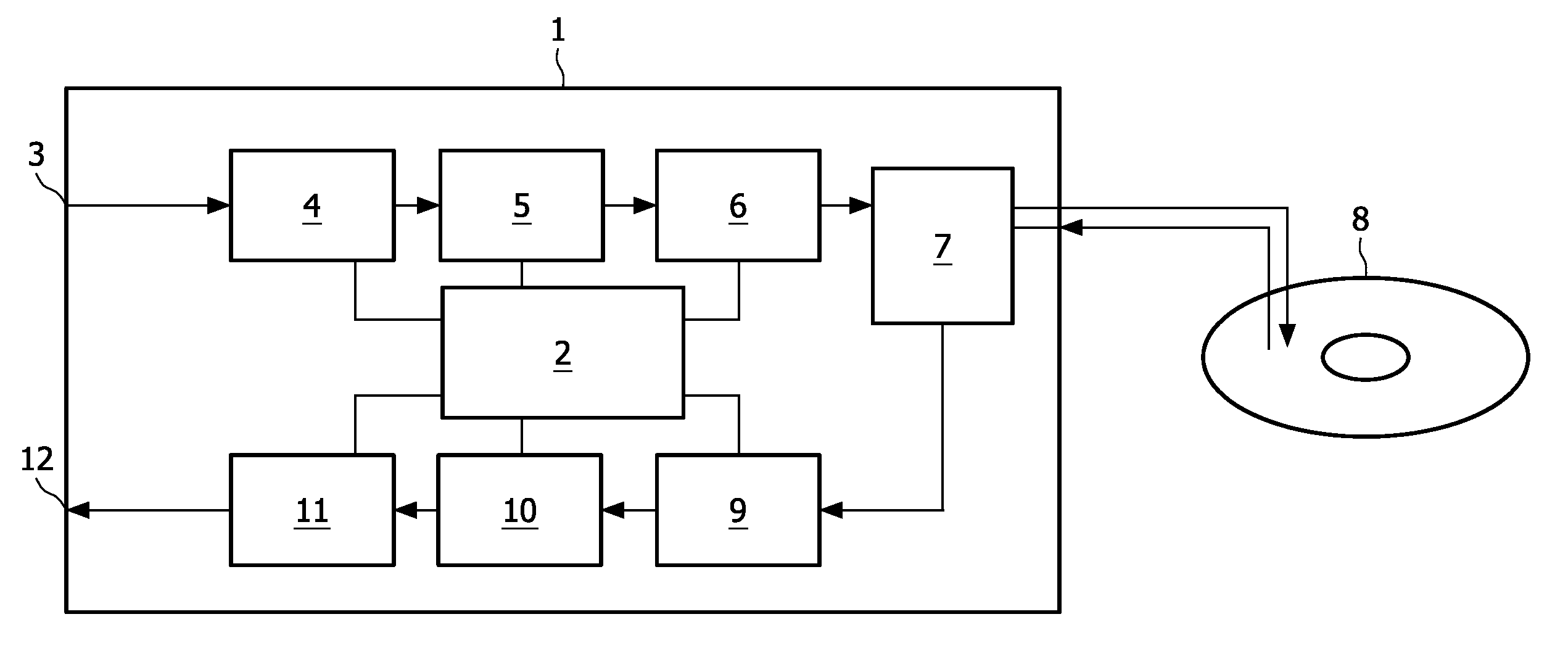
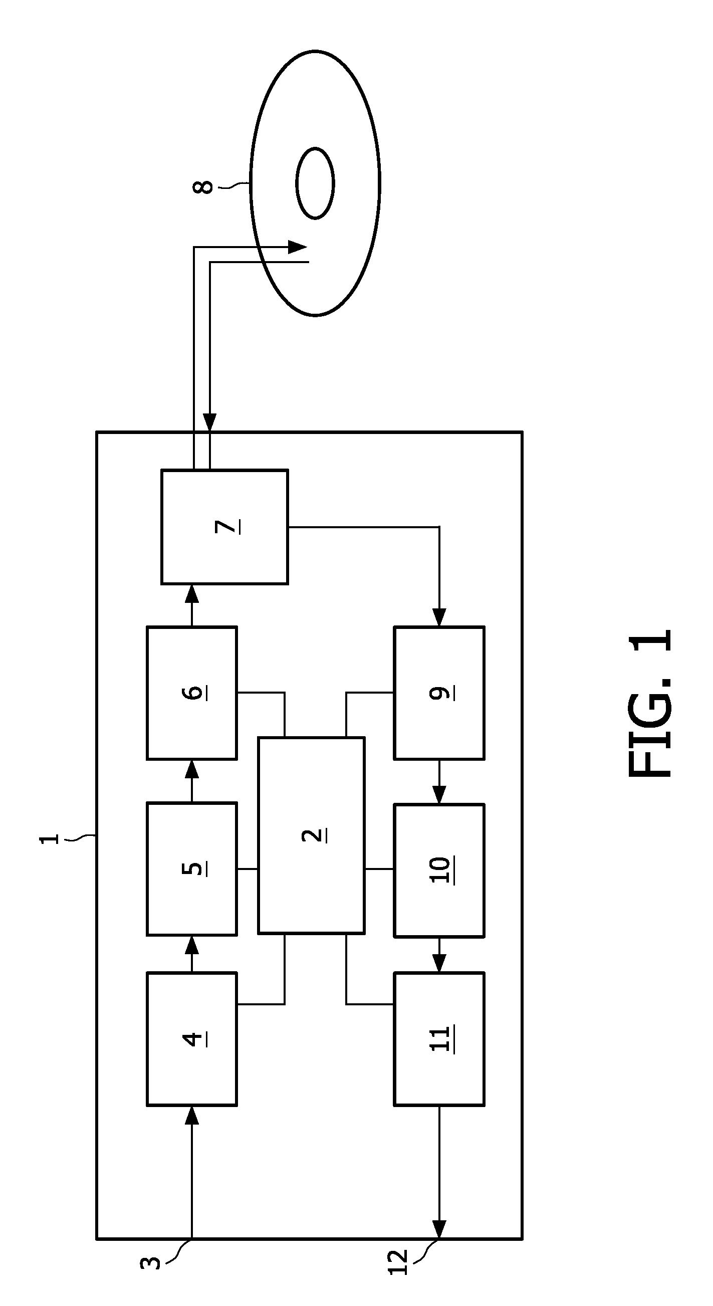
[0057]FIG. 1 shows a block diagram of a recording device.

[0058]The recording device 1 is arranged for recording user data received on input 3 on the optical record carrier 8. For this, the recording device 1 comprises a data formatter 4. The data formatter 4 receives the user data from the input 3 and determines in what format the user data must be recorded on the optical disc 8. The resulting formatted data is provided by the data formatter 4 to the error correction encoder 5 that applies an error correction code to the data received from the data formatter 4. This error correction encoded data is subsequently provided by the error correction coder 5 to the channel coder 6. The channel coder 6 applies a channel code to the error correction encoded data so that the error correction encoded data is more suitable to be recorded on the optical disc 8. The channel encoder 6 for instance applies a run length limited code with constraints to the error correction encoded data. Another more...


PUM


Abstract

A visible pattern is obtained by modulating the digital sum value. Because the digital sum value modulation allows the choice of several different channel bits groups between DC control points, the selection of a group of channel bits resulting in a change of reflection. This creation of a visible pattern is highly suitable for Blueray as the parity preserving property of the channel code guarantees disparity inversion by the DC-control bit, which keeps the DSV excursions between hard limits. As a result only small DSV deliberate variations are required to produce a visual watermark, which will not deteriorate the bit-detection margin of the optical disc.

Description

FIELD OF THE INVENTION[0001]The invention relates to an optical disc comprising[0002]a track,[0003]a plurality of channel bits located in the track,[0004]the plurality of channel bits having a Digital Sum Value,[0005]the Digital Sum Value having a set point determined by a DC control,[0006]the DC control being limited within a DC Control rangeBACKGROUND OF THE INVENTION[0007]Such a disc is known from U6496541 where a channel code for recording an optical disc is disclosed. This 17PP channel code is parity preserving. To create watermarks on the optical disc such a code is extended with extra code words so that when encoding a choice exists between code words that yield higher or lower reflectivity. This is however not always possible if most code words are already used by the code and not many additional unused code words are available, so that the result is of low quality because not always the optimal reflectivity can be obtained. In addition adding extra code words to the code me...

Claims


Application Information

Patent Timeline
IPC IPC(8): G11B3/70G11B7/00G11B7/24094
CPCG11B7/24094G11B20/00086G11B20/0013G11B20/00173G11B2220/2541G11B20/00884G11B20/14G11B23/281G11B23/40G11B20/00579G11B20/10G11B7/007
Inventor MARIA KAHLMAN, JOSEPHUS ARNOLDUS HENRICUSDEN HOLLANDER, JACOBUS MAARTEN
Owner KONINKLIJKE PHILIPS ELECTRONICS NV
Why Eureka
Try Eureka