Illumination device having broad lighting distribution

a technology of illumination device and illumination device, which is applied in the direction of semiconductor devices for light sources, free standing, light and heating apparatus, etc., can solve the problem of hard replacement of all conventional illumination bulbs by conventional led illumination devices, and achieve the effects of improving luminance, increasing reflection angle, and enhancing luminance of illumination devices

Active Publication Date: 2015-11-19
EPISTAR CORP
View PDF4 Cites 0 Cited by
  • Summary
  • Abstract
  • Description
  • Claims
  • Application Information

AI Technical Summary

Benefits of technology

[0020]The illumination device of the present invention includes the micro-structures for increasing the reflection angle of the light emitted from the semiconductor light emitting element. The micro-structures are disposed on the first illuminating part so as to reflect the light downward to achieve abroad or an all-directional light distribution, and the shape and size of the micro-structures are optimized for better luminance. Accordingly, a luminance of the illumination device is enhanced and a lighting distribution of the illumination device is improved.

Problems solved by technology

However, a light beam emitted from the LED is a kind of directional light source, and is different from the traditional dispersive light source.
This is the reason why it is hard to replace all conventional illumination bulbs by the conventional LED illumination devices.

Method used


Image

  • Illumination device having broad lighting distribution
  • Illumination device having broad lighting distribution
  • Illumination device having broad lighting distribution

Examples


sixth embodiment

[0042]Please refer to FIG. 10. FIG. 10 is a cross-sectional diagram of an illumination device 7 according to the present invention. In contrast to the above embodiments of the present invention, the lamp housing 54 of the illumination device 7 may further include a second illuminating part 841 above the first illuminating part 541. At least a part of the lateral illuminating part 543 couples the first illuminating part 541 and the second illuminating part 841, and surrounds a space which is formed between the first illuminating part 541 and the second illuminating part 841. The second illuminating part 841 includes a plurality of micro-structures 845 disposed on a side of the second illuminating part 841 and faced the semiconductor light emitting element 50. The micro-structures 845 can reflect at least a part of the light which is emerged from the first illuminating part 541. Another side of the second illuminating part 841, corresponding to the side facing the semiconductor light ...

seventh embodiment

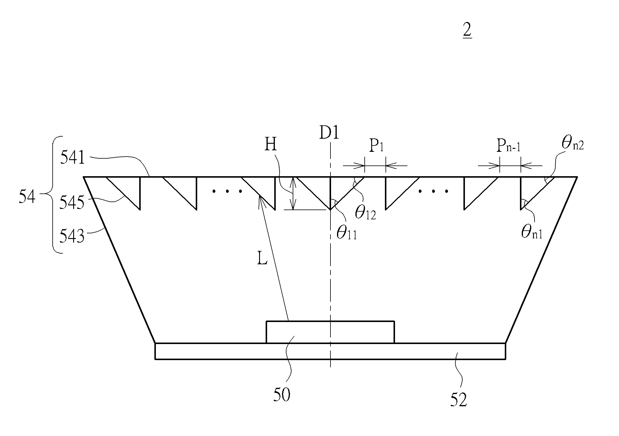
[0043]Please refer to FIG. 11. FIG. 11 is a top view of an illumination device 8 according to the present invention. In contrast to the above embodiments of the present invention, the illumination device 8 may include a plurality of semiconductor light emitting elements 50. The semiconductor light emitting elements 50 may be symmetrically disposed corresponding to a center part of the supporting base 52. The first illuminating part 541 or the second illuminating part 841 may be shaped as a circle, and the supporting base 52 may be shaped as a circle, square or other different shape corresponding to the shape of the illuminating part 541 or 841. The plurality of the micro-structures 545 (845) may be grouped into different reflection sections 547 (847). In cross-section view, each reflection section 547 (847) may include a plurality of V-cut sections and a plurality of triangles, wherein the V-cut sections and the triangles are symmetrically concentrically disposed corresponding to a ...


PUM


Abstract

An illumination device includes at least one semiconductor light emitting element, a supporting base, and a lamp housing. The semiconductor light emitting element is disposed on the supporting base. The lamp housing is disposed on the supporting base to cover the semiconductor light emitting element, and includes a first illuminating part and a lateral illuminating part surrounding the first illuminating part. A micro-structure is formed on a side of the first illuminating part and facing the semiconductor light emitting element for reflecting the light emitted from the semiconductor light emitting element.

Description

BACKGROUND OF THE INVENTION[0001]1. Field of the Invention[0002]The present invention relates to an illumination device, and more specifically, to an illumination device including a semiconductor light emitting element and a micro-structure and having broad lighting distribution.[0003]2. Description of the Prior Art[0004]As the growth of the technology, a light emitting diode (LED) is widespread inhuman life. LED has advantages such as fast response, small size, low pollution, low power consumption, high reliability, and long service life, and is applied for illumination or for displaying. A conventional illumination bulb, such as an incandescent bulb, can be replaced by an LED illumination device. However, a light beam emitted from the LED is a kind of directional light source, and is different from the traditional dispersive light source. This is the reason why it is hard to replace all conventional illumination bulbs by the conventional LED illumination devices.[0005]Please refer...

Claims


Application Information

Patent Timeline
Patent Type & Authority Applications(United States)
IPC IPC(8): F21K99/00
CPCF21K9/58H01L33/58H01L33/54F21V3/02F21V3/04F21V7/22F21K9/65
Inventor YE, ZHI-TINGCHIEN, FEN-REN
Owner EPISTAR CORP
Why Eureka
Try Eureka