Solar-infrared hybrid collector

a solar-infrared and hybrid collector technology, applied in the direction of thermal-pv hybrid energy generation, electrical equipment, semiconductor devices, etc., can solve the problem of not increasing the system footprint of solar-infrared hybrid collectors, and achieve the effect of increasing the annual collector energy output and maximizing the utilization of collectors

Active Publication Date: 2015-12-03
GAS TECH INST
View PDF7 Cites 3 Cited by
  • Summary
  • Abstract
  • Description
  • Claims
  • Application Information

AI Technical Summary

Benefits of technology

[0006]A general object of the invention is to provide a solar-infrared hybrid collector that addresses key problems with current solar technologies, such as high capital cost per unit power output, low utilization factor and low or no energy production when solar intensity drops or during the night. The invention is suitable for residential, commercial, industrial, and power generation customers as it allows significant increases in the utilization factor / throughput of concentrated photovoltaics (CPV) collectors and concentrated solar thermal (CST) collectors, also known as concentrated solar power (CSP). Benefits compared to current CPV and CST technologies include: two to three times higher annual output from the same size collector with no changes to balance of the plant; on-demand generation of heat and electricity without the need to store energy; reduced equipment footprint per unit energy output; and potentially significantly reduced costs per unit energy output.
[0009]The reflector of this invention may comprise one of a variety of shapes including, for example, a substantially parabolic dish, a substantially parabolic trough, a compound parabolic dish, a compound parabolic trough, a planar mirror and a plurality of mirror segments forming a curved and / or angled shape. The reflector is preferably coated on an incident side to maximize reflection of solar radiation and infrared radiation and to minimize absorption of solar radiation and infrared radiation. When using the substantially parabolic dish, the receiver is preferably located proximate to a focal point of the substantially parabolic dish. When using the substantially parabolic trough, the receiver is preferably located proximate to an axis of the substantially parabolic trough. When using the compound parabolic dish, the receiver is preferably located in proximity to dual focal points of the compound parabolic dish. When using the compound parabolic trough, the receiver is preferably located in proximity to dual axis of the compound parabolic trough. In an alternative embodiment, the reflector may instead comprise a focusing lens, such as a Fresnel lens, to focus solar radiation on the receiver. In an embodiment of this invention, the reflector may include a heat exchanger or heat sink to prevent the reflector from overheating.
[0011]With this design, the solar-infrared hybrid collector provides significant improvement over conventional solar collectors. Even in relatively sunny locations like California, an average annual irradiance is only 22% of peak irradiance, the solar-hybrid collector of this invention maximizes utilization of the collector and increases an annual collector energy output by two to three times without significant changes to the plant.

Problems solved by technology

With this design, the system footprint of the solar-infrared hybrid collector is not increased over the size of conventional solar collectors.

Method used


Image

  • Solar-infrared hybrid collector
  • Solar-infrared hybrid collector
  • Solar-infrared hybrid collector

Examples


Embodiment Construction

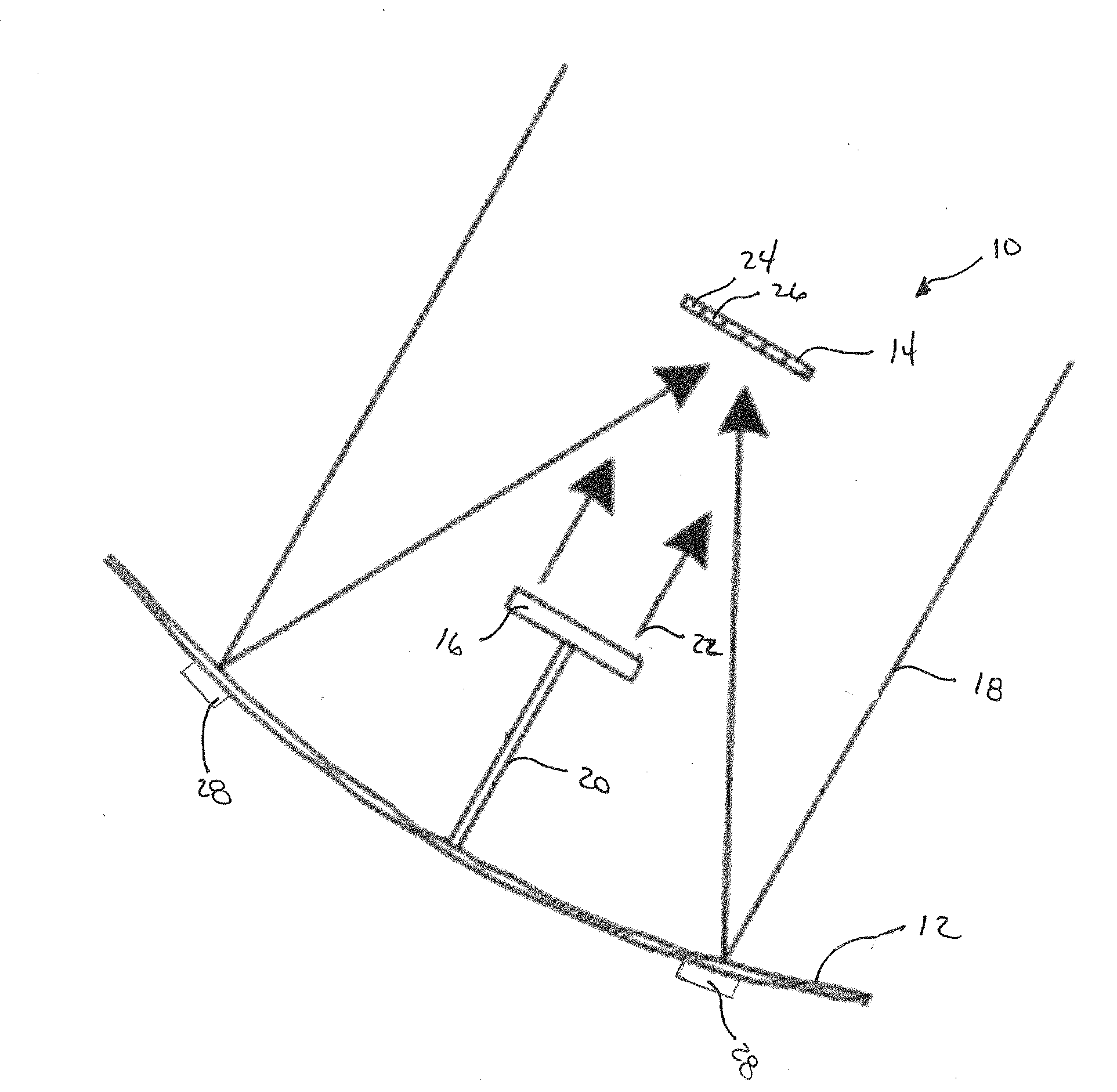
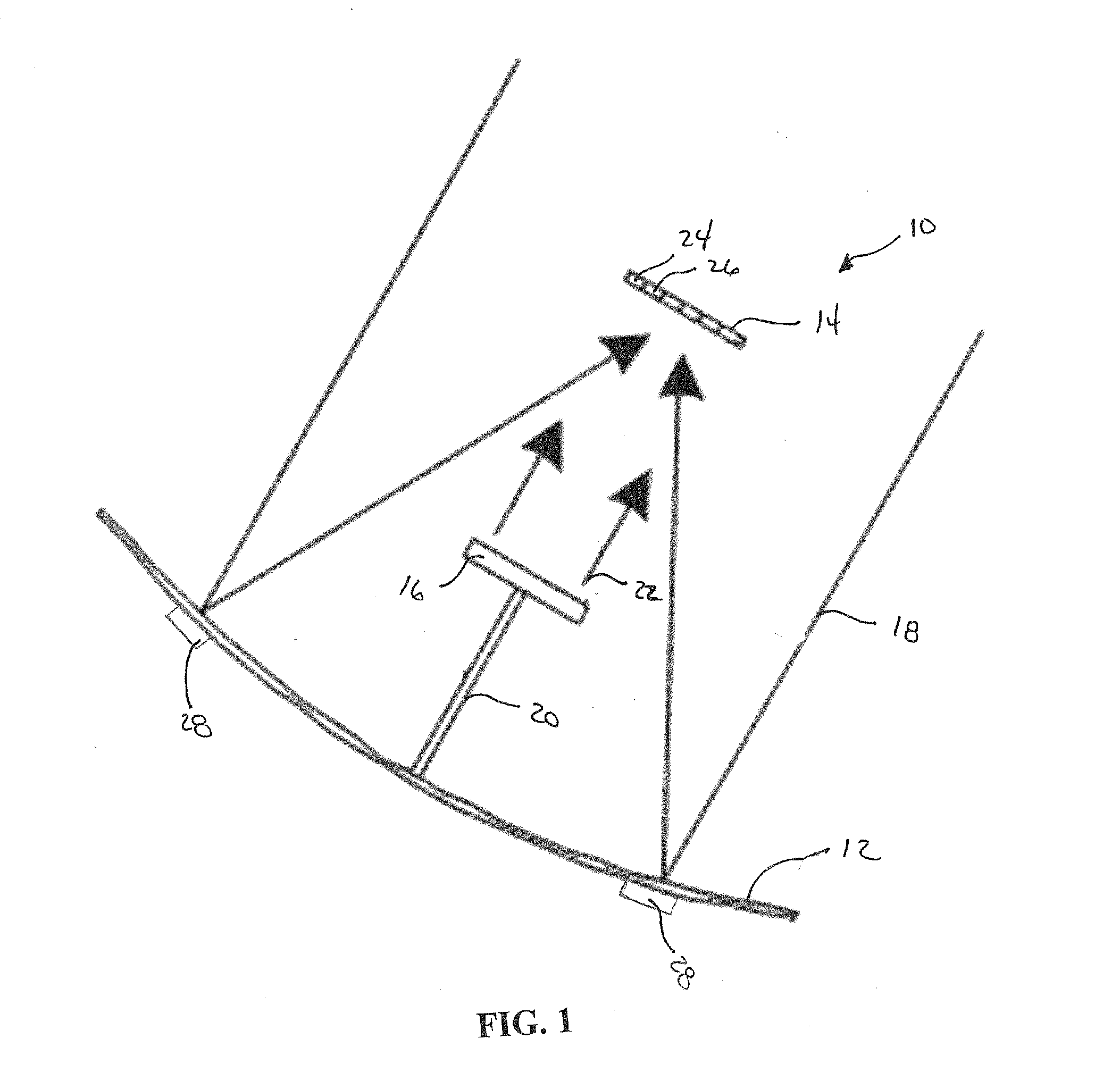
[0021]The present invention provides an improved solar collector including an infrared heater to provide thermal and electric output during times of low or no solar intensity.

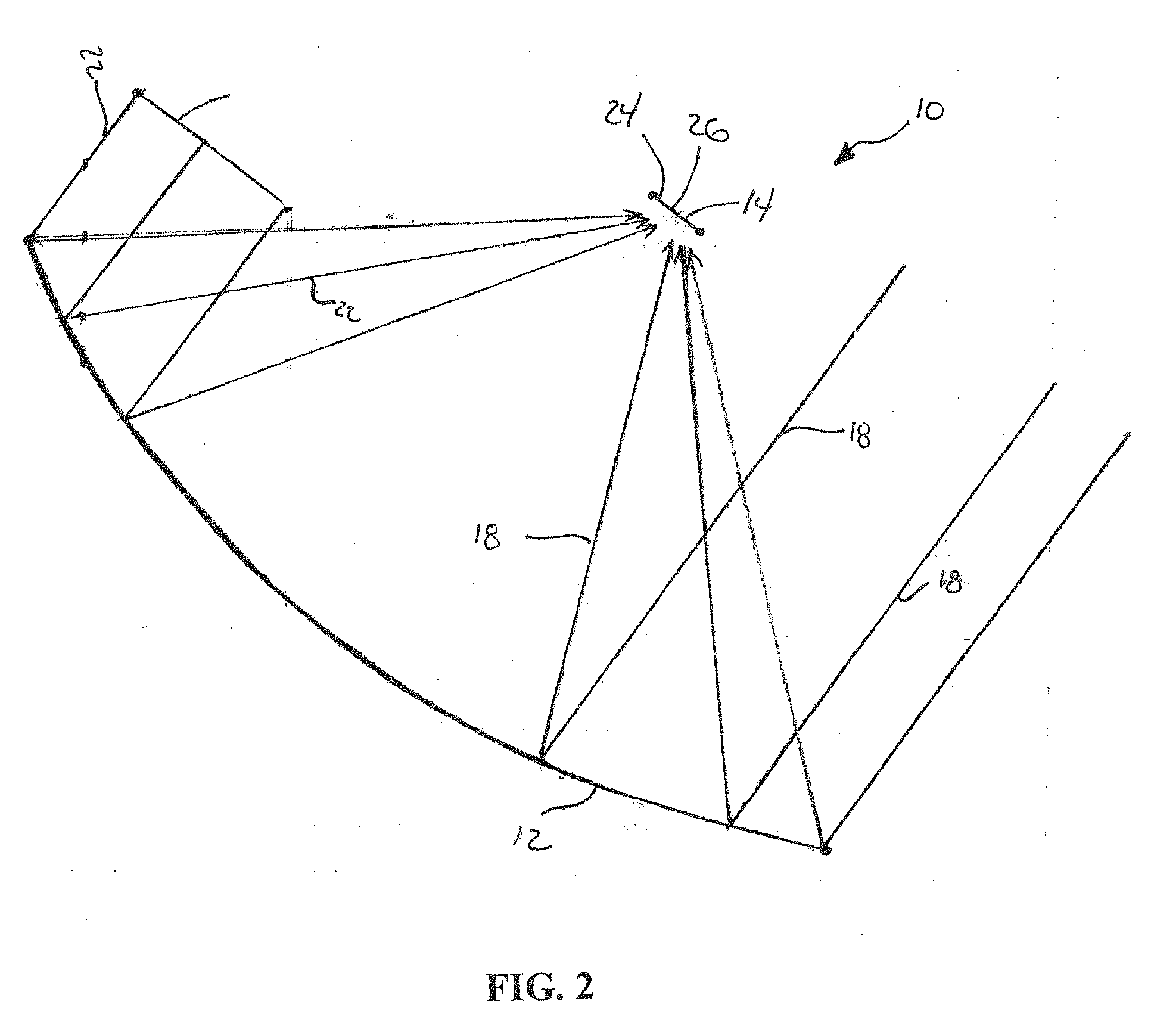
[0022]FIG. 1 shows a solar-infrared hybrid collector 10 according to an embodiment of this invention. In this embodiment, the solar-infrared hybrid collector includes a reflector 12, a receiver 14 and an infrared heater 16, also known as an IR burner. As shown in FIG. 1, the reflector 12 is positioned in proximity to the receiver 14 to reflect solar radiation 18 from the sun to the receiver 14 and the infrared heater 16 is positioned on a mounting mechanism to project infrared radiation 22 directly to the receiver 14. In another embodiment, as shown in FIG. 2, the infrared heater 16 is positioned to shine infrared radiation 22 off the reflector 12 to the receiver 14. In another embodiment of this invention, as shown in FIG. 3, the solar-infrared hybrid collector 10 may not include a reflector. In this embodimen...


PUM


Abstract

A system and method for improving solar collector design to provide thermal and electric output during times of low or no solar intensity. The improved solar collector design includes an infrared heater to supplement energy provided by the sun during time of low or no solar intensity.

Description

CROSS REFERENCE TO RELATED APPLICATION(S)[0001]This application claims the benefit of U.S. Provisional Patent Application Ser. No. 62 / 004,627, filed on 29 May 2014. The co-pending Provisional Application is hereby incorporated by reference herein in its entirety and is made a part hereof, including but not limited to those portions which specifically appear hereinafter.BACKGROUND OF THE INVENTION[0002]1. Field of the Invention[0003]This invention relates to an improved solar collector including an infrared heater to provide electricity and thermal energy during times of high and low solar energy and even in absence of solar radiation.[0004]2. Discussion of Related Art[0005]Solar energy systems, including solar collectors, generate electricity and thermal energy from the sun. Known systems generally include a curved mirror or a lens to focus sunlight onto a receiver which includes photovoltaic cells and / or a heat exchanger to generate electricity and to collect thermal energy. Howeve...

Claims


Application Information

Patent Timeline
Patent Type & Authority Applications(United States)
IPC IPC(8): H02S10/30
CPCH02S10/30H02S40/22H02S40/44Y02E10/52Y02E10/60
Inventor ABBASI, HAMID ALICYGAN, DAVID F.
Owner GAS TECH INST
Why Eureka
Try Eureka