Recording apparatus

Active Publication Date: 2015-12-31
SEIKO EPSON CORP
View PDF4 Cites 0 Cited by
  • Summary
  • Abstract
  • Description
  • Claims
  • Application Information

AI Technical Summary

Benefits of technology

[0029]In this case, the discharge roller is located below the second frame material. As a result, the size of the discharge roller and the size of the second frame material are

Problems solved by technology

However, the driving roller is connected to a power source and cannot freely rotate.
Thus, upon comparison with the driven roller, the dr

Method used


Image

  • Recording apparatus
  • Recording apparatus
  • Recording apparatus

Examples


Example

[0054]Hereinafter, an embodiment of the invention will be described with reference to the accompanying drawings. However, the invention is not limited to the embodiment described below. The embodiment can be modified in various ways as long as they are within the scope of the invention described in the claims. The embodiment of the invention will be described with a precondition that the modified embodiments are included in the scope of the invention.

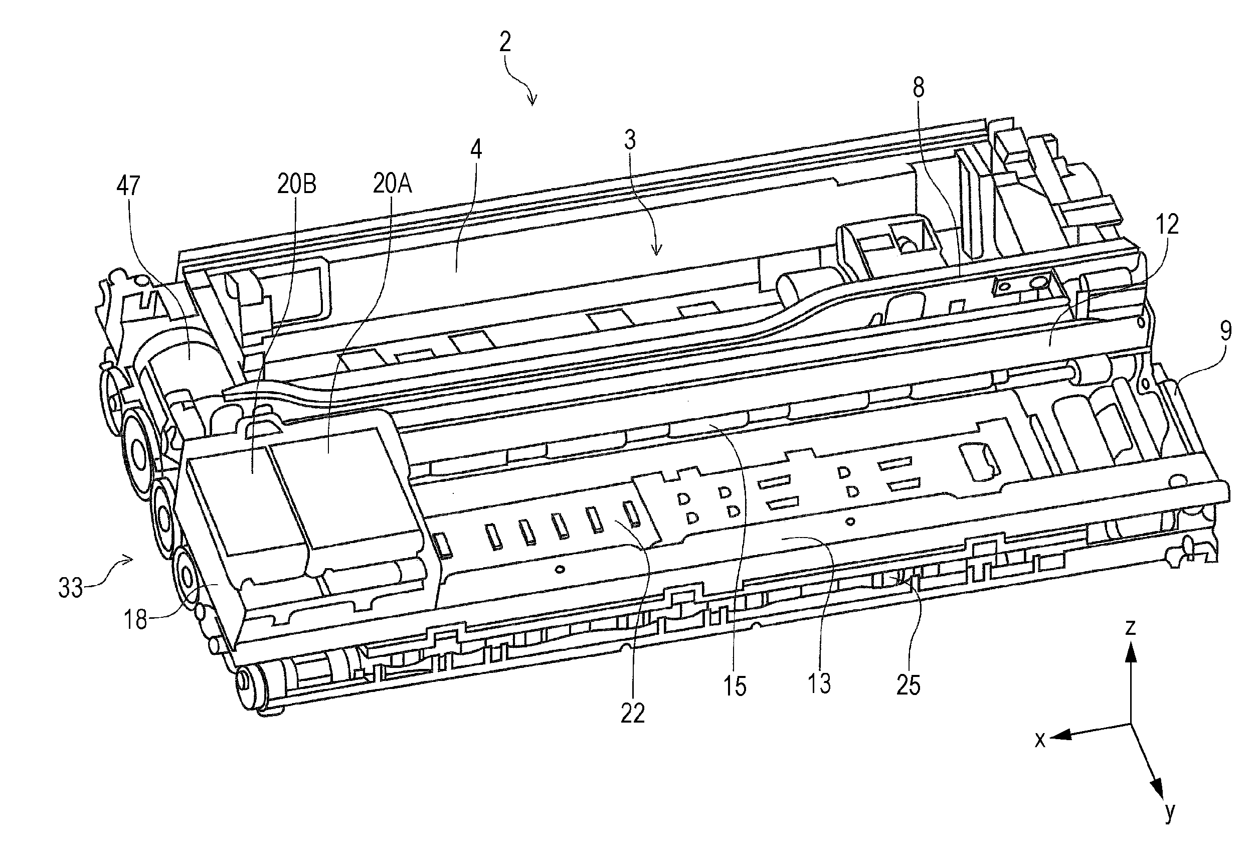
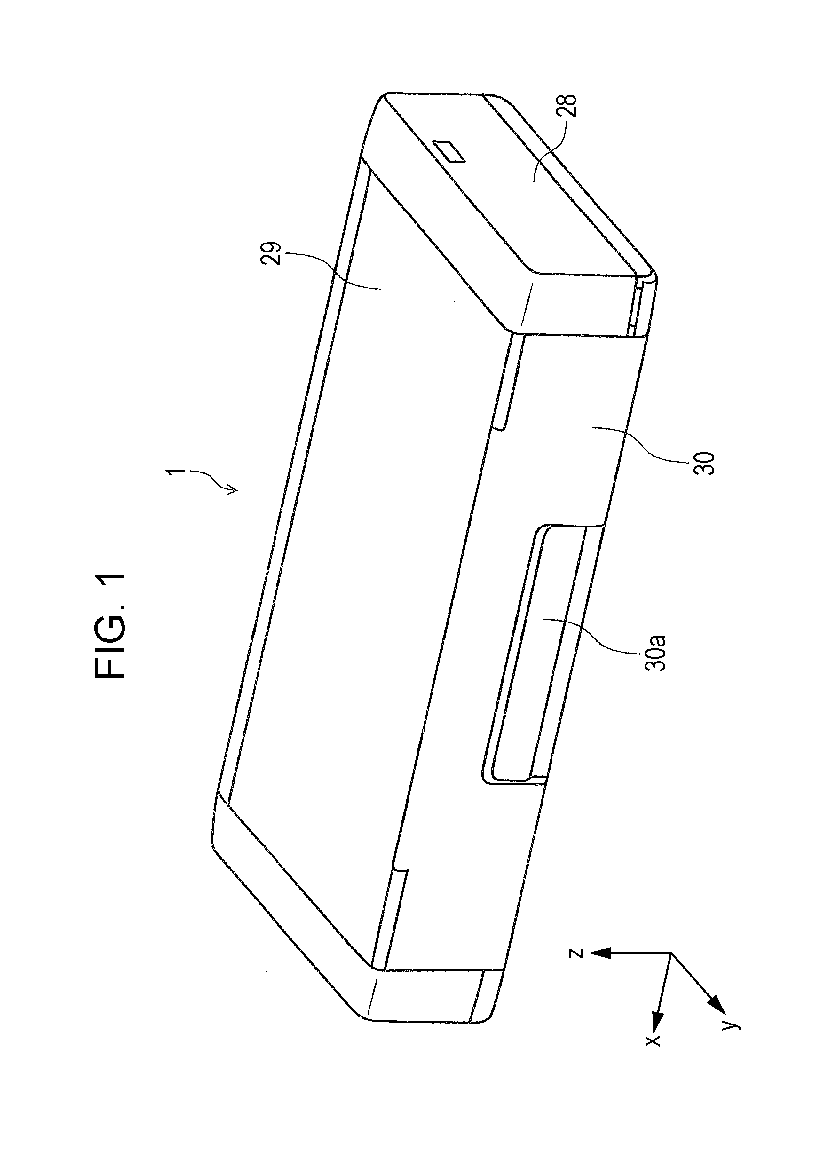
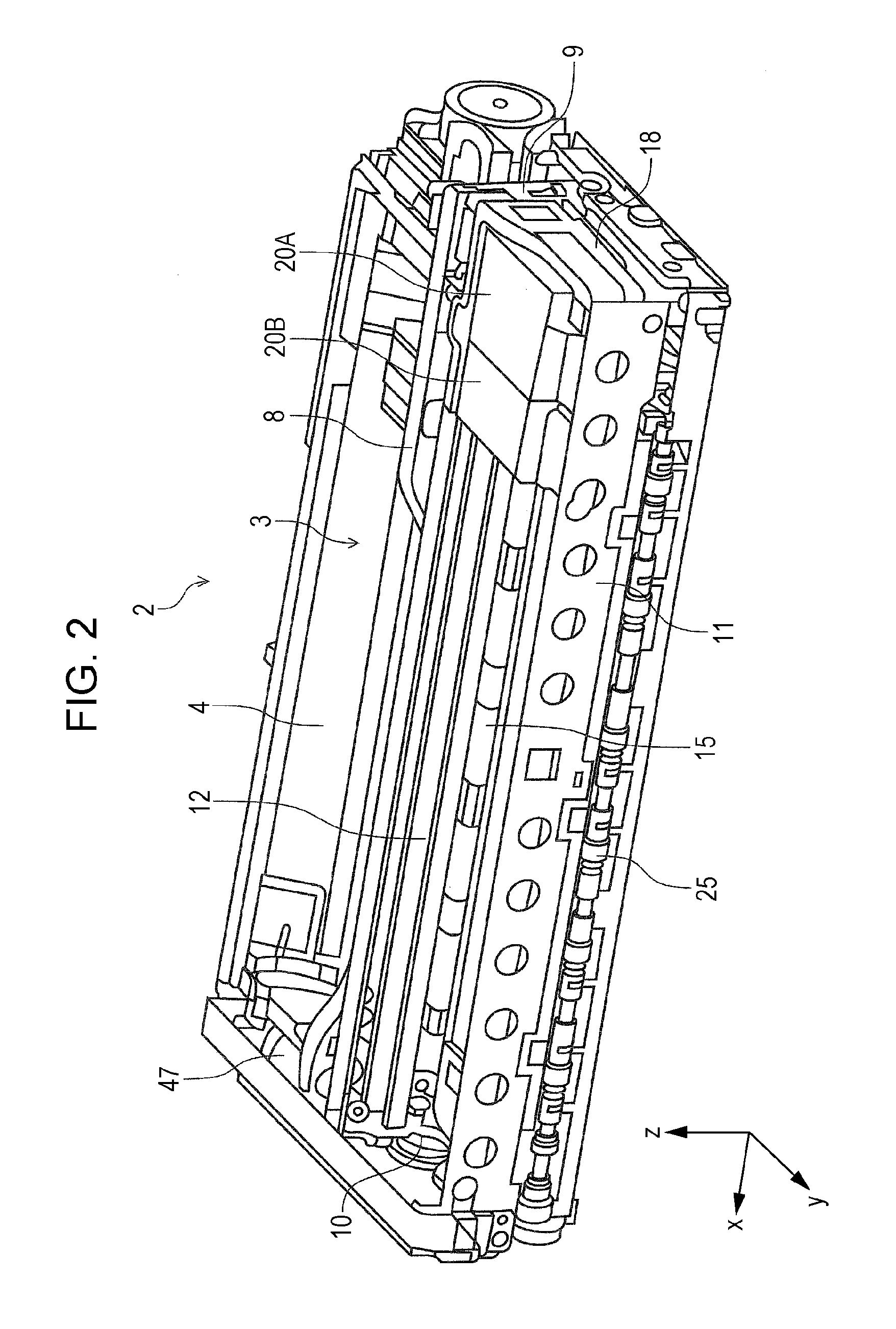
[0055]FIG. 1 is a perspective view of an external appearance of an ink jet printer (hereinafter, referred to as a “printer”) 1 as an embodiment of a “recording apparatus” according to the invention. FIGS. 2 and 3 are perspective views of an apparatus main body (in a state where a casing body forming the external appearance is removed) 2. FIG. 4 is a lateral cross-sectional view illustrating a paper transport path of the printer 1 according to the invention. FIGS. 5 and 6 are partially enlarged views of FIG. 4.

[0056]Furthermore, FIG. 7 i...


PUM


Abstract

Provided is a printer which includes a carriage which includes a recording head performing recording on a paper sheet, a transport driving roller which transports the paper sheet to the recording head side and is driven by a driving source, and a transport driven roller which is pressed to the transport driving roller, is rotationally driven in contact with the paper sheet, and has a diameter larger than that of the transport driving roller. The transport driving roller is located below a guide frame as a support member supporting the carriage and is located in an area of the guide frame in a paper transport direction (in other words, a y direction).

Description

BACKGROUND[0001]1. Technical Field[0002]The present invention relates to a recording apparatus represented by a facsimile or a printer.[0003]2. Related Art[0004]In an ink jet printer as an example of a recording apparatus, a pair of transport rollers which transport a recording paper sheet as an example of a medium is provided on an upstream side of a recording head. Generally, the pair of transport rollers is constituted of a driving roller driven by a motor and a driven roller pressed to the driving roller.[0005]There is a so-called serial-type printer in which a carriage including a recording head can move in a scanning direction of the recording head. In such a serial-type printer, the carriage is supported by a support member (in other words, a guide member) and is guided in the scanning direction of the recording head. An example of such a serial-type recording apparatus is disclosed in JP-A-2006-247932.[0006]Examples of the support member supporting the carriage include a sha...

Claims


Application Information

Patent Timeline
IPC IPC(8): B41J11/04
CPCB41J3/36B41J29/023B41J2/1752B41J29/02B41J29/13B41J29/38B41J11/04
Inventor SAKAMOTO, NAOKISHUTO, RYOICHI
Owner SEIKO EPSON CORP
Why Eureka
Try Eureka