Terminal group and connector

Active Publication Date: 2016-08-11
YAZAKI CORP
View PDF6 Cites 6 Cited by
  • Summary
  • Abstract
  • Description
  • Claims
  • Application Information

AI Technical Summary

Benefits of technology

[0027]According to the connector having the configuration according to (8), when the plurality of pin terminals of the terminal group are press-fitted in the plurality of terminal insertion holes of the connector housing, respectively, the insertion direction rear end side surfaces of the press-fitting supports, which are formed at the same positions from the distal ends of the pin terminals in the insertion direction regardless of the different overall lengths of the plurality of pin terminals, are supported by an insertion jig or the like, and thus, it is possible to always receive reaction force of the press-fitting of the pin terminals which are pr

Problems solved by technology

However, when the board terminal 505 or the board terminal 511 illustrated in FIG. 11 and FIG. 13 is inserted into the terminal insertion hole 525 or a terminal holding hole 515 of a housing, the rear end portion of the board terminal 505 or the board t

Method used


Image

  • Terminal group and connector
  • Terminal group and connector
  • Terminal group and connector

Examples


Example

[0043]Hereinafter, an embodiment of the present invention will be described with reference to the drawings.

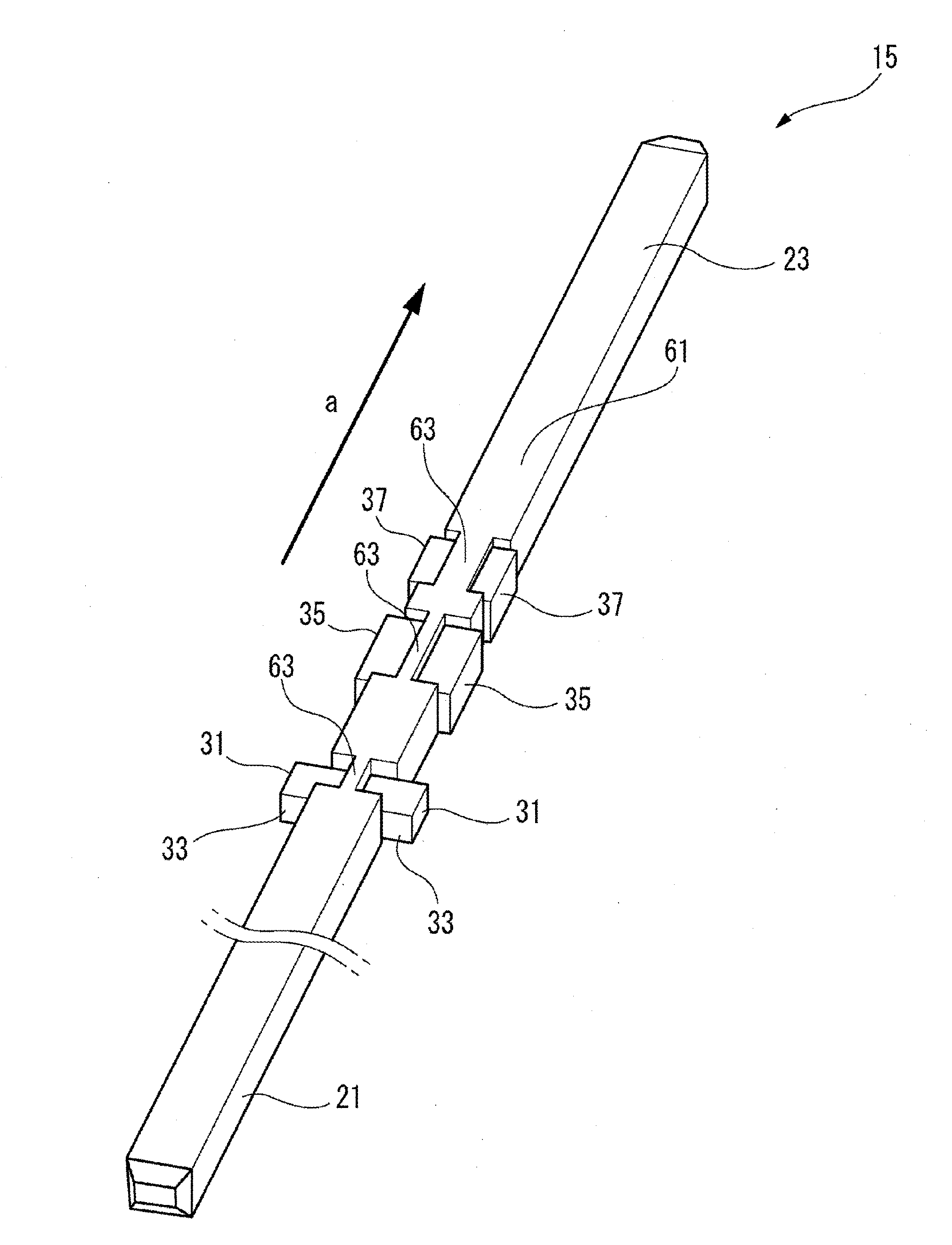
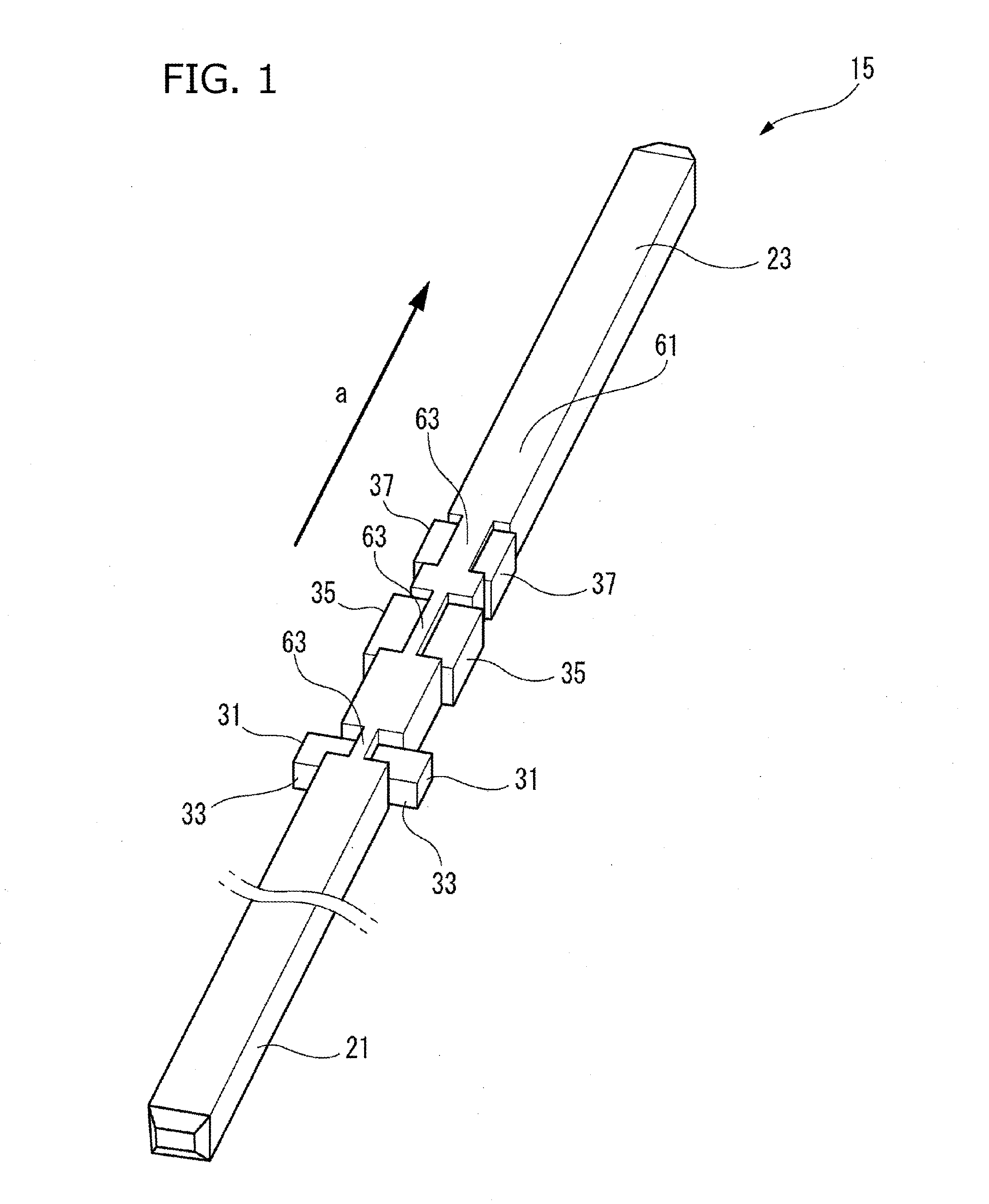
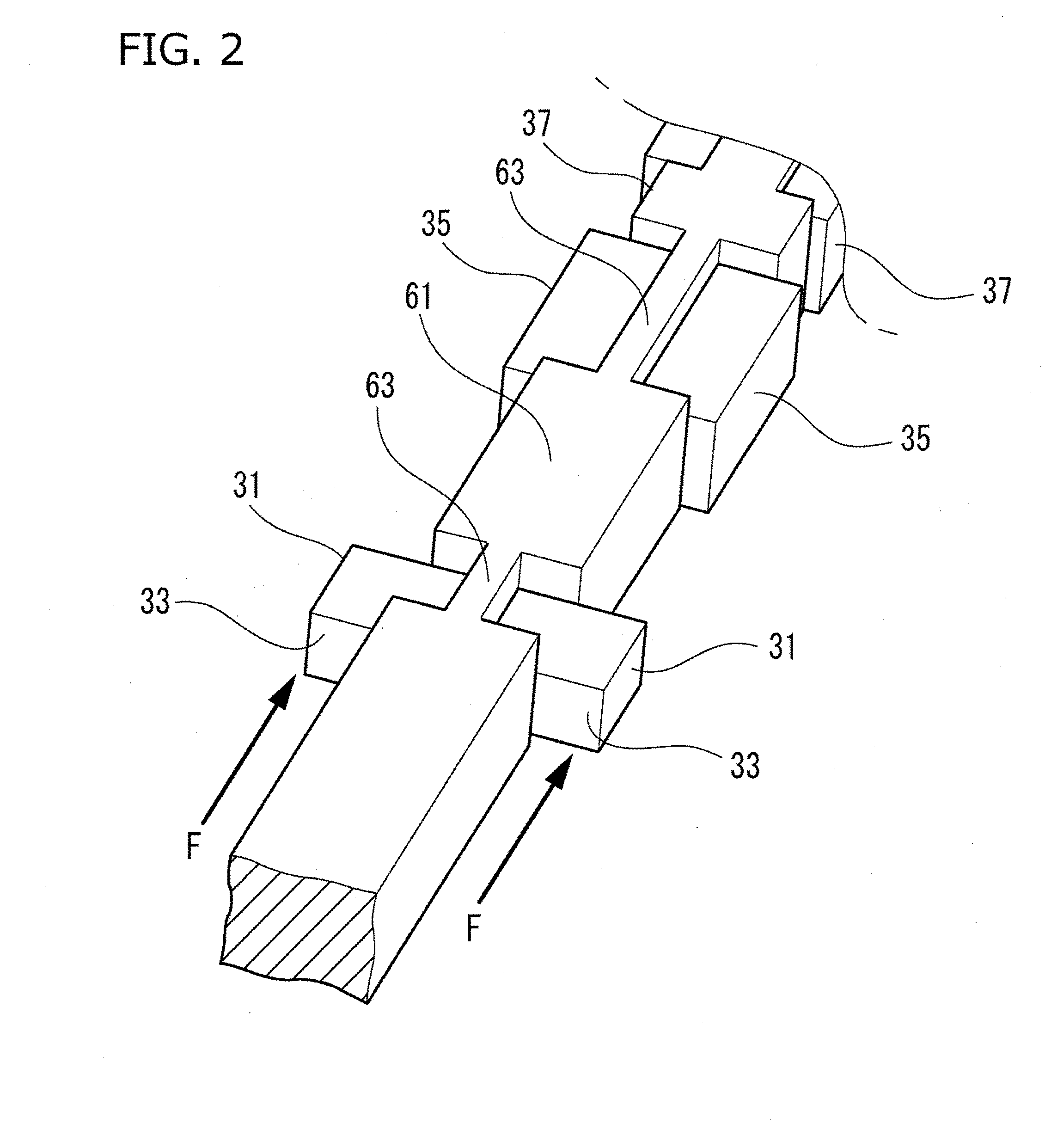
[0044]A terminal group 11 (refer to FIGS. 5 and 6) of a plurality of pin terminals 15 according to an embodiment of the present invention is applied to a board connector 13 (refer to FIG. 6) which is a connector. The board connector 13 is installed on a printed circuit board (not illustrated) in which, for example, an electrical junction box of an automobile is accommodated. The terminal group 11 consists of the plurality of pin terminals 15. The pin terminals 15 are formed by cutting an elongated conductive metal wire by a predetermined length and are press-fitted and held in a plurality of terminal insertion holes 19 of a connector housing 17 (refer to FIG. 6) . The pin terminal 15 is bent such that one end side (board connecting portion 21) is formed to an L shape and then is soldered to a conduction path of the printed circuit board (not illustrated), and the other end side...


PUM


Abstract

A terminal group includes: a plurality of pin terminals, each pin terminal being formed of a metal wire of a predetermined length and being to be press-fitted and held in each of a plurality of terminal insertion holes of a connector housing. Some of the plurality of pin terminals have different overall lengths. The plurality of pin terminals respectively have a pair of press-fitting supports that protrude from both side edges of each of the plurality of pin terminals in a width direction at the same distant positions from a distal end in an insertion direction, and insertion direction rear end side surfaces of the press-fitting supports receive reaction force with respect to the terminal insertion holes in press-fitting.

Description

CROSS REFERENCE TO RELATED APPLICATION[0001]This application is based on Japanese Patent Application (No. 2015-023335) filed on Feb. 9, 2015, and Japanese Patent Application (No. 2015-102970) filed on May 20, 2015, the contents of which are incorporated herein by reference. Also, all the references cited herein are incorporated as a whole.BACKGROUND OF THE INVENTIONTechnical Field[0002]One or more embodiments of the invention relate to a terminal group and a connector.[0003]In the related art, a board connector 501 as illustrated in FIG. 11 is used as a board connector for wire connection with a circuit board. The board connector 501 includes a synthetic resin connector housing 503 formed to have substantially a rectangular parallelepiped shape, as a whole, and a plurality of board terminals 505 provided to protrude from the connector housing 503. Also, the board terminal 505 is formed to have an L shape with both a base end portion 507 provided to horizontally protrude from the con...

Claims


Application Information

Patent Timeline
IPC IPC(8): H01R13/422
CPCH01R13/422H01R12/55H01R13/40H01R12/58H01R12/724H01R13/41H01R43/22
Inventor KAWAGISHI, MIKAOHYAMA, KOUICHI
Owner YAZAKI CORP
Why Eureka
Try Eureka