Speed change apparatus

Active Publication Date: 2009-07-02
AISIN AW CO LTD
View PDF1 Cites 6 Cited by
  • Summary
  • Abstract
  • Description
  • Claims
  • Application Information

AI Technical Summary

Benefits of technology

[0004]In this type of speed change apparatus, two clutch drums are disposed in two concentric layers such that two clutches can be accommodated in a compact manner, thereby reducing the overall size of the apparatus. However, when clutch drums are disposed in two layers, the size of each clutch drum in a r

Problems solved by technology

However, when clutch drums are disposed in two layers, the size of each clutch drum in a radial direction is restricted, and

Method used


Image

  • Speed change apparatus
  • Speed change apparatus
  • Speed change apparatus

Examples


Example

[0014]Next, a detailed description of the preferred embodiment will be described using an embodiment of the present invention.

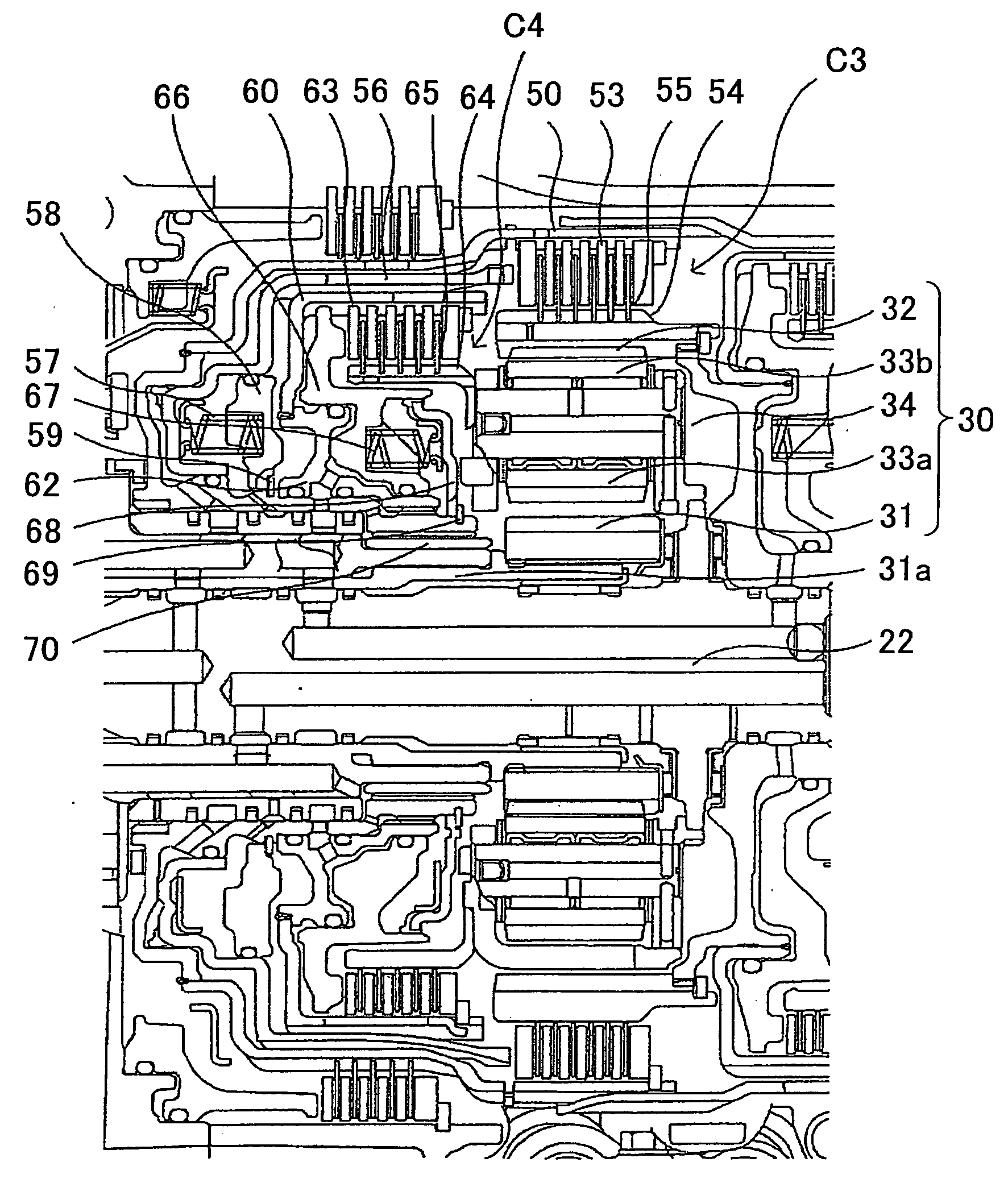
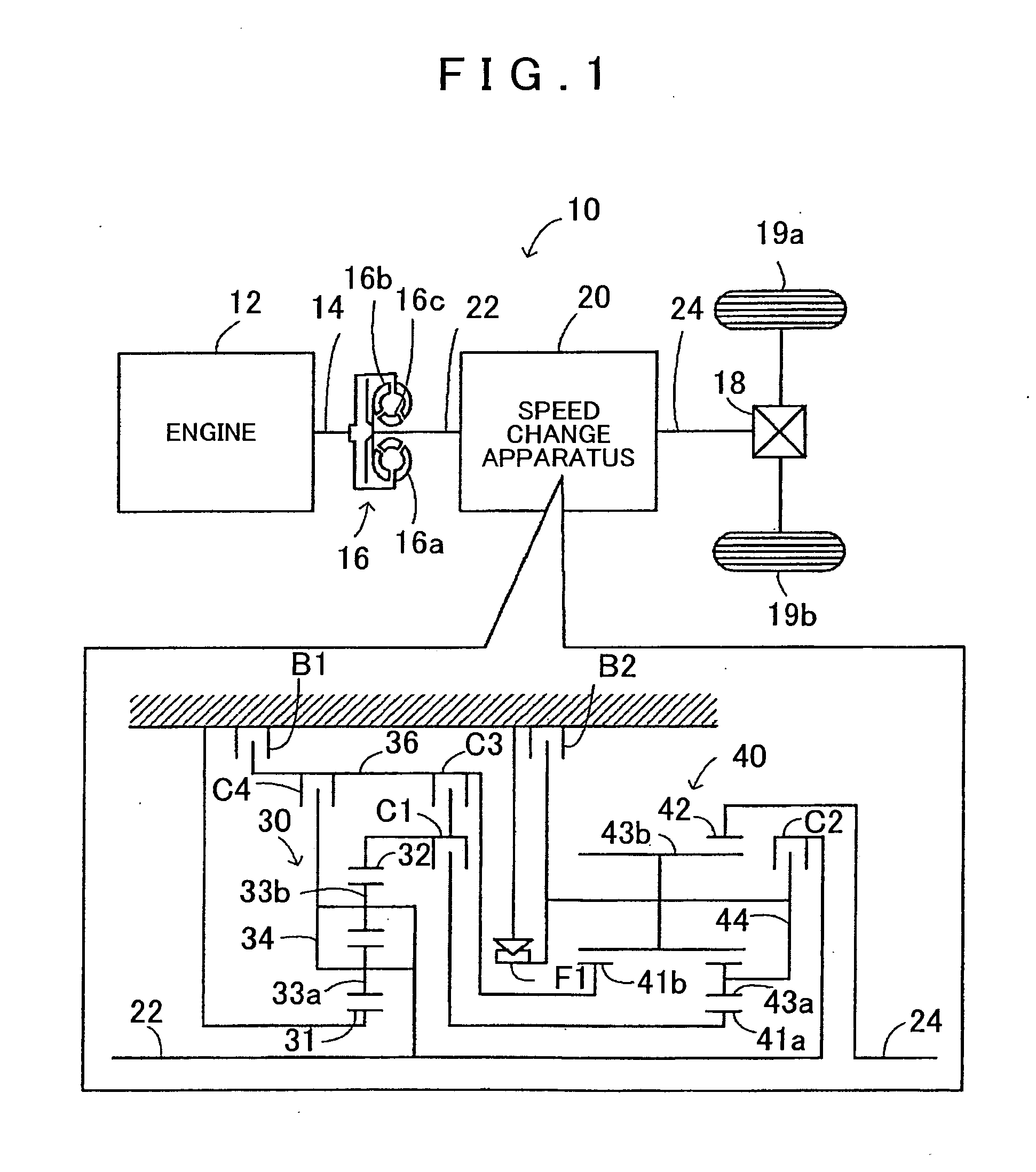
[0015]FIG. 1 is a schematic diagram showing the structure of an automobile 10 in which a speed change apparatus 20 serving as an embodiment of the present invention is installed. As shown in the drawing, the automobile 10 according to this embodiment includes an engine 12 serving as an internal combustion engine that outputs power by igniting and burning a hydrocarbon-based fuel such as gasoline or light oil, a torque converter 16 attached to a crankshaft 14 of the engine 12, and the speed change apparatus 20, which serves as a stepped transmission in which an input shaft 22 is connected to an output side of the torque converter 16 and an output shaft 24 is connected to drive wheels 19a, 19b via a differential gear 18, and which changes the speed of power input into the input shaft 22 and transmits the speed-changed power to the output shaft 24. The automobil...


PUM


Abstract

A speed change apparatus includes a first clutch having a first clutch drum, in which an annular clutch plate is spline-fitted to an inner peripheral surface of the first clutch drum, and a clutch piston formed with a spline on an inner peripheral surface of the clutch piston is provided to slide in an axial direction and press the clutch plate; and a second clutch having a second clutch drum, which is disposed in the clutch piston of the first clutch concentrically with the first clutch, and in which a spline is formed on inner and outer peripheral surfaces of the second clutch drum such that outer peripheral surface spline teeth form inner peripheral surface spline grooves. Wherein the outer peripheral surface of the second clutch drum is spline-fitted to the inner peripheral surface of the clutch piston and an annular clutch plate is spline-fitted to the inner peripheral surface of the second clutch drum.

Description

INCORPORATION BY REFERENCE[0001]The disclosure of Japanese Patent Application No. 2007-338776 filed on Dec. 28, 2007 including the specification, drawings and abstract is incorporated herein by reference in its entirety.BACKGROUND[0002]The present invention relates to a speed change apparatus.[0003]There exits a speed change apparatus that is installed in an automobile and that changes a shift speed by switching the engagement of a plurality of clutches (see Japanese Patent Application Publication No. JP-A-2006-349162, for example). A clutch provided in this speed change apparatus is a multi-plate clutch in which a plurality of clutch plates are disposed alternately on a clutch drum attached to one rotary body and a clutch hub is attached to another rotary body. The two rotary bodies are connected by pressing the clutch plates using a clutch piston.SUMMARY[0004]In this type of speed change apparatus, two clutch drums are disposed in two concentric layers such that two clutches can b...

Claims


Application Information

Patent Timeline
IPC IPC(8): F16H3/44
CPCF16D13/683F16D25/0638F16D25/10F16D2048/0212F16H3/663F16H2200/2048F16H2200/006F16H2200/0086F16H2200/2007F16H2200/2046F16H3/666
Inventor ISHII, TAKUYATODO, MINORU
Owner AISIN AW CO LTD
Why Eureka
Try Eureka