Laser processing apparatus

Active Publication Date: 2011-04-14
DISCO CORP
View PDF5 Cites 7 Cited by
  • Summary
  • Abstract
  • Description
  • Claims
  • Application Information

AI Technical Summary

Benefits of technology

[0009]It is therefore an object of the present invention to provide a laser processing apparatus which can perform laser processing on the whole of the workpiece with the size of the apparatus reduced even in the case that any one of the plural laser oscillating means becomes abnormal and cannot oscillate a laser beam.
[0011]According to the present invention, the plural first focusing lenses corresponding to the first laser oscillating means and the plural second focusing lenses corresponding to the second laser oscillating means are alternately arranged in the indexing direction. Accordingly, the distance between the focusing lenses located at the opposite ends of the array of the plural focusing lenses corresponding to each laser oscillating means can be made longer than that in a prior art configuration such that a plurality of focusing lenses corresponding to each laser oscillating means are juxtaposed. With the configuration of the present invention, in the case that either the first laser oscillating means or the second laser oscillating means becomes abnormal and cannot oscillate a laser beam, it is possible to suppress an increase in the amount of relative movement of the holding table and the laser applying means in the indexing direction by the indexing means. Accordingly, laser processing can be performed on the whole of the workpiece with the size of the apparatus reduced.

Problems solved by technology

However, in the case that two laser oscillating means are used and a laser beam from each laser oscillating means is branched into plural laser beams to be applied to a workpiece, there is a problem when any one of the two laser oscillating means becomes abnormal and cannot oscillate a laser beam.
Accordingly, when any one of the two laser oscillating means becomes abnormal, the laser applying position cannot be positioned to all of the work lines, so that laser processing cannot be performed on the whole of the workpiece.
In assuming that any one of the two laser oscillating means becomes abnormal and cannot oscillate a laser beam, the amount of movement of the laser applying position and / or the workpiece must be ensured to perform laser processing on the whole of the workpiece, causing an increase in size of a laser processing apparatus.
In the case that the laser processing apparatus cannot be increased in size, the operation of the apparatus must be stopped at the time any one of the laser oscillating means becomes abnormal.

Method used


Image

  • Laser processing apparatus
  • Laser processing apparatus
  • Laser processing apparatus

Examples


Embodiment Construction

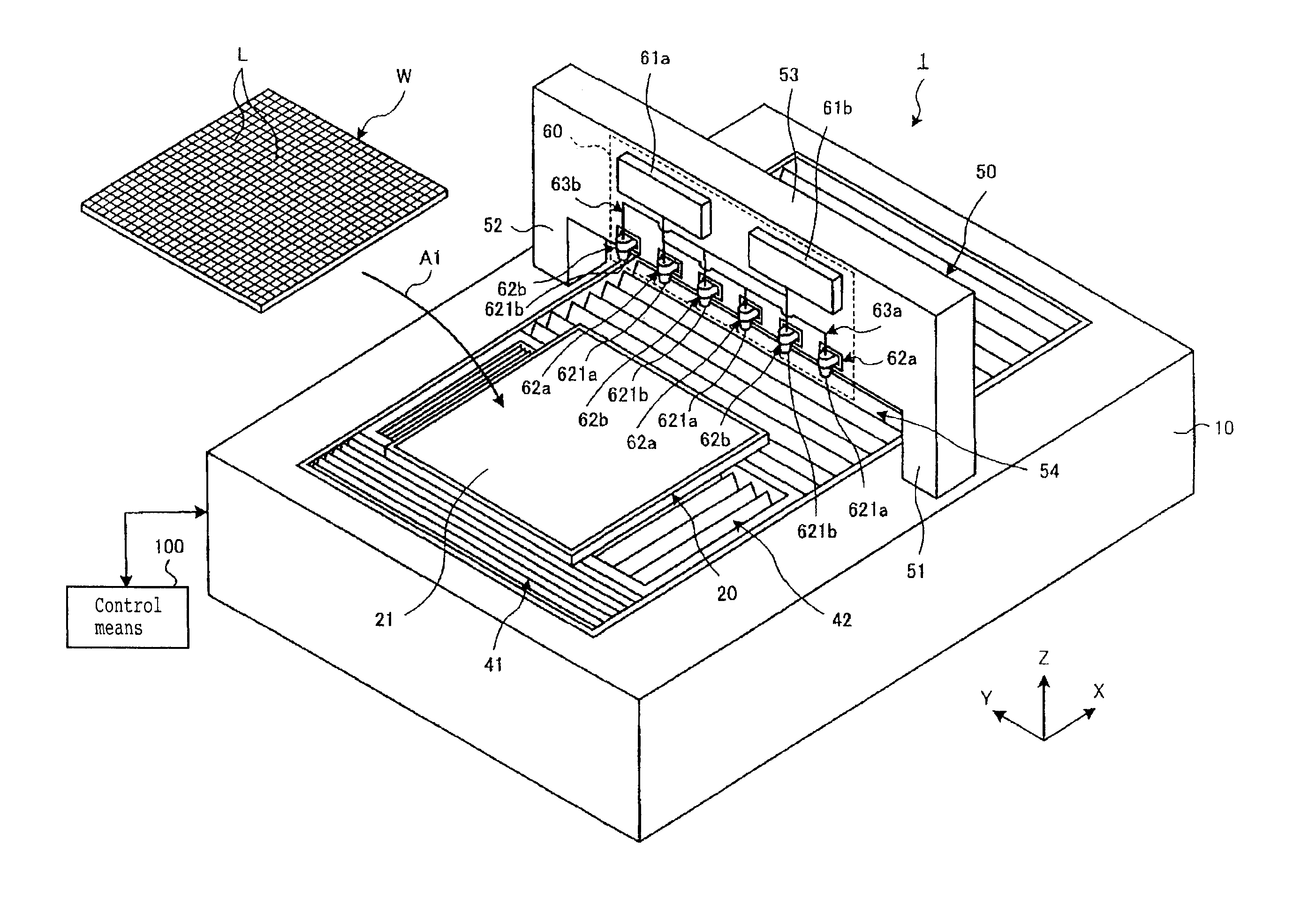
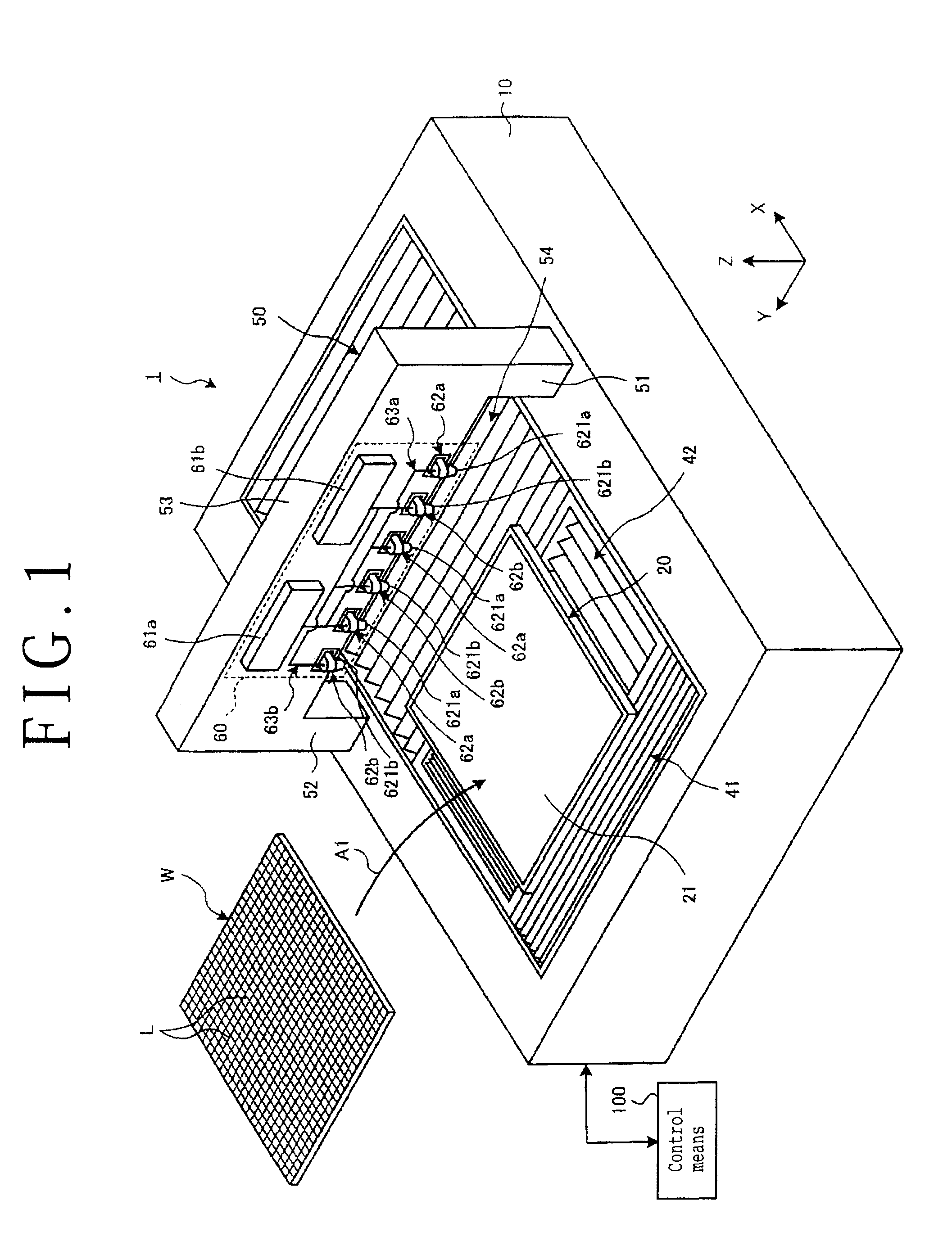
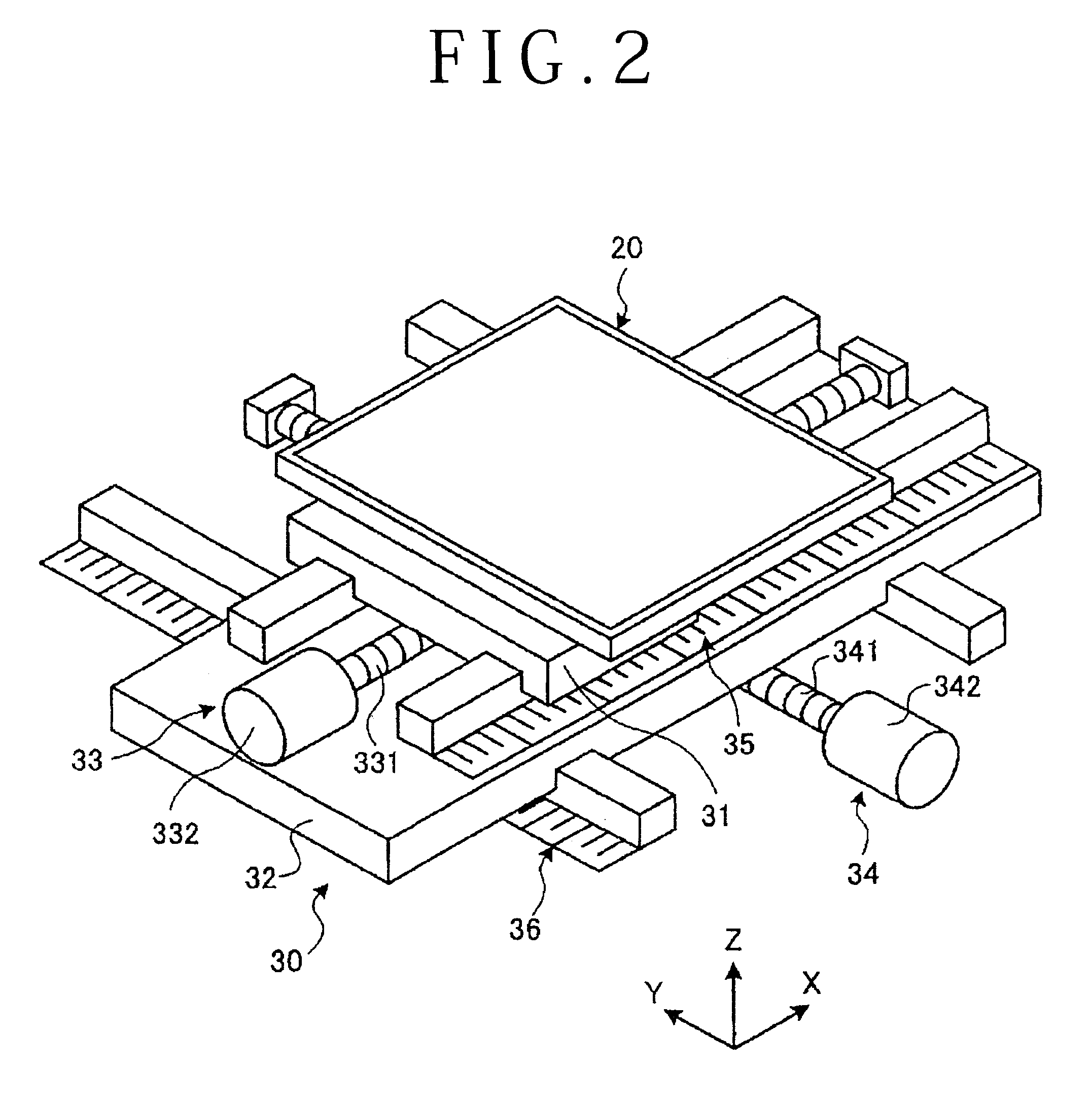
[0026]A preferred embodiment of the laser processing apparatus according to the present invention will now be described with reference to the drawings. FIG. 1 is a schematic perspective view for illustrating the configuration of an essential part of a laser processing apparatus 1 according to a preferred embodiment of the present invention and the configuration of a glass substrate W as an example of the workpiece to be laser-processed by the laser processing apparatus 1. FIG. 2 is a schematic perspective view for illustrating the configuration of holding table driving means 30.

[0027]As shown in FIG. 1, the glass substrate W to be laser-processed by the laser processing apparatus 1 is a rectangular platelike glass substrate, for example, and the work surface of the glass substrate W (the upper surface as viewed in FIG. 1) is formed with a plurality of crossing work lines L. The glass substrate W is laser-processed along these work lines L by the laser processing apparatus 1. While t...


PUM


Abstract

A laser processing apparatus including a laser applying unit. The laser applying unit includes a first laser oscillating unit, a second laser oscillating unit, a first laser branching unit for branching a laser beam oscillated from the first laser oscillating unit into three optical paths, a second laser branching unit for branching a laser beam oscillated from the second laser oscillating unit into three optical paths, three first focusing units for respectively focusing the laser beams through the three optical paths obtained by the first laser branching unit toward a glass substrate, and three second focusing units for respectively focusing the laser beams through the three optical paths obtained by the second laser branching unit. The first focusing units and the second focusing units are alternately arranged in a line in an indexing direction.

Description

BACKGROUND OF THE INVENTION[0001]1. Field of the Invention[0002]The present invention relates to a laser processing apparatus for laser-processing a workpiece such as a semiconductor wafer and a glass substrate.[0003]2. Description of the Related Art[0004]In a fabrication process for electronic parts, a plurality of crossing work lines called streets are formed on the front side of a workpiece such as a semiconductor wafer and a glass substrate to thereby partition a plurality of regions where a plurality of functional devices are respectively formed. The workpiece thus formed with the functional devices is divided along the work lines to thereby produce the individual electronic parts.[0005]Known is a laser processing method such that a laser beam is applied to a workpiece to thereby perform laser processing along the work lines. For example, Japanese Patent Laid-open No. 10-305420 discloses a method of applying a laser beam to a workpiece such as a wafer to thereby form a groove o...

Claims


Application Information

Patent Timeline
IPC IPC(8): B23K26/06B23K26/00B23K26/08B23K26/364
CPCB23K26/0673C03B33/0222B23K26/0853
Inventor TOGASHI, KENNOMARU, KEIJIMORIKAZU, HIROSHI
Owner DISCO CORP
Why Eureka
Try Eureka