In-box quick release access device structure

Active Publication Date: 2015-12-31
CHENBRO MICOM
View PDF11 Cites 11 Cited by
  • Summary
  • Abstract
  • Description
  • Claims
  • Application Information

AI Technical Summary

Benefits of technology

[0008]The present invention has been accomplished under the circumstances in view. It is therefore the main object of the present invention to provide an in-box quick release access device mounting structure, which is adapted for selectively holding one of two different sizes of access devices without using screws or any hand tool.
[0009]To achieve this and other objects of the present invention, an in-box quick release access device mounting structure of the invention comprises a holder shell made of a rigid material, and a retaining mechanism made of an elastic plastic material. The holder shell comprises a bottom panel, opposing first and second side panels respectively and vertically upwardly extended from two opposite lateral sides of the bottom panel, an accommodation chamber surrounded by the bottom panel and the first and second side panels, a first locating member obliquely extended from the bottom panel adjacent to the second side panel, a mounting space defined in the accommodation chamber and surrounded by the first positioning member and the first locating member, a second positioning member located in the first side panel at a relatively higher elevation than the first positioning member, and a second locating member located in the second side panel. The retaining mechanism comprises a first retaining plate fastened to the first locating member and facing toward the first positioning member, and a second retaining plate fastened to the s

Problems solved by technology

In a small sized electronic equipment, the number of communication ports and recording media and apparatus (disk drive, hard disk, CD-ROM, burner programmer, etc.) is limited.
It takes much time and labor to mount or dismount a media storage device, complicating the maintenance or replacement work.
If the server case or cabinet housing has a low profile, the internal interface cards, hard disks and cables can hinder the mounting and dismounting of the screws.
During the mounting or dismounting operation, screws can get

Method used


Image

  • In-box quick release access device structure
  • In-box quick release access device structure
  • In-box quick release access device structure

Examples


Embodiment Construction

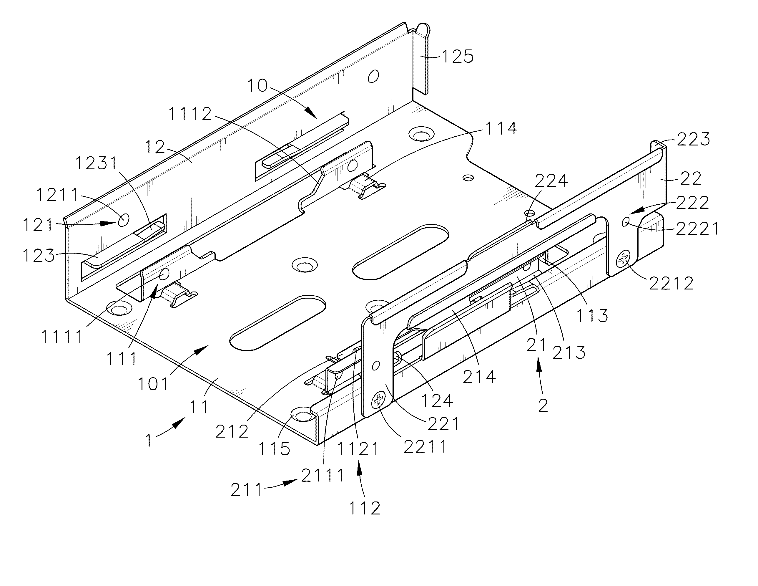
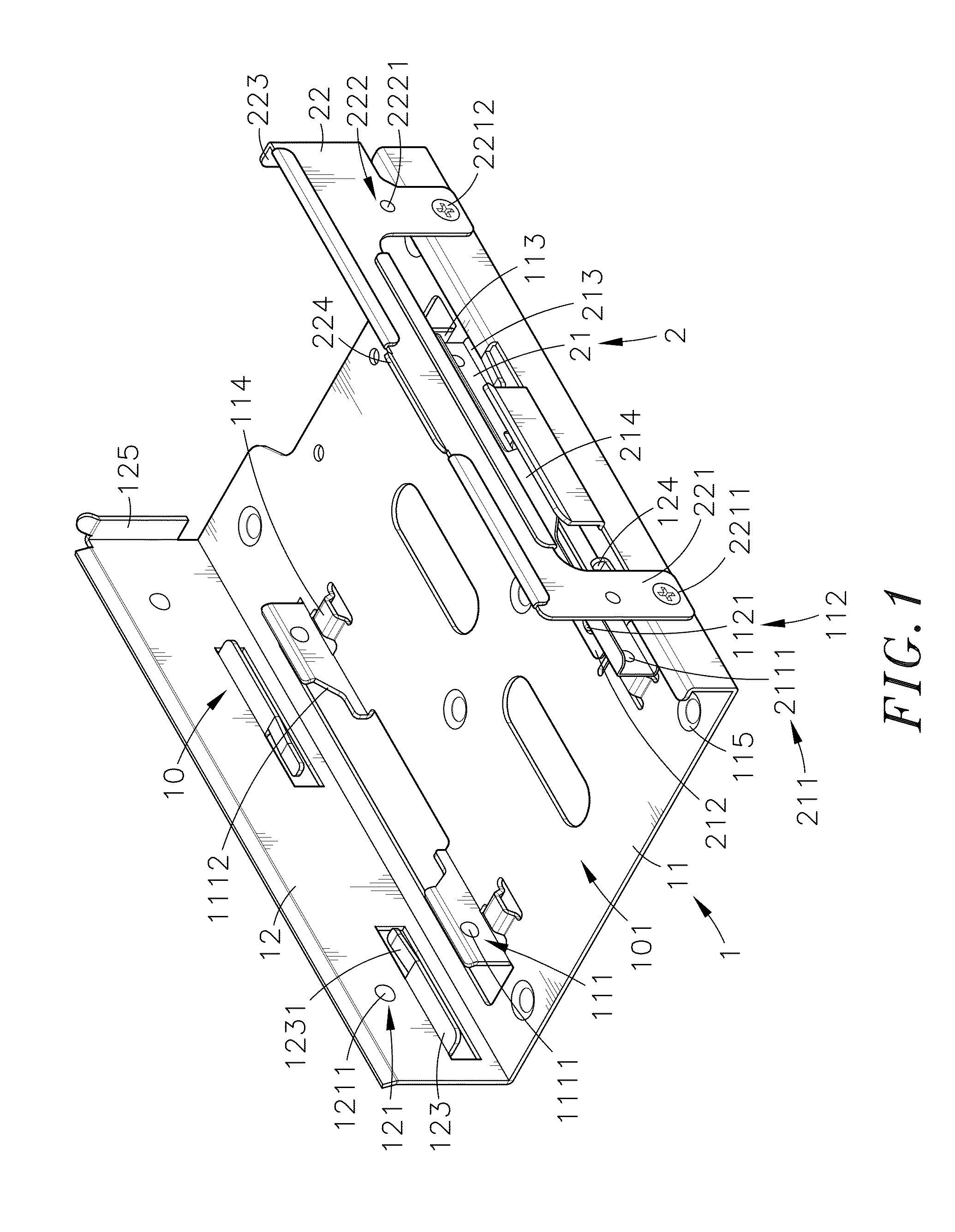
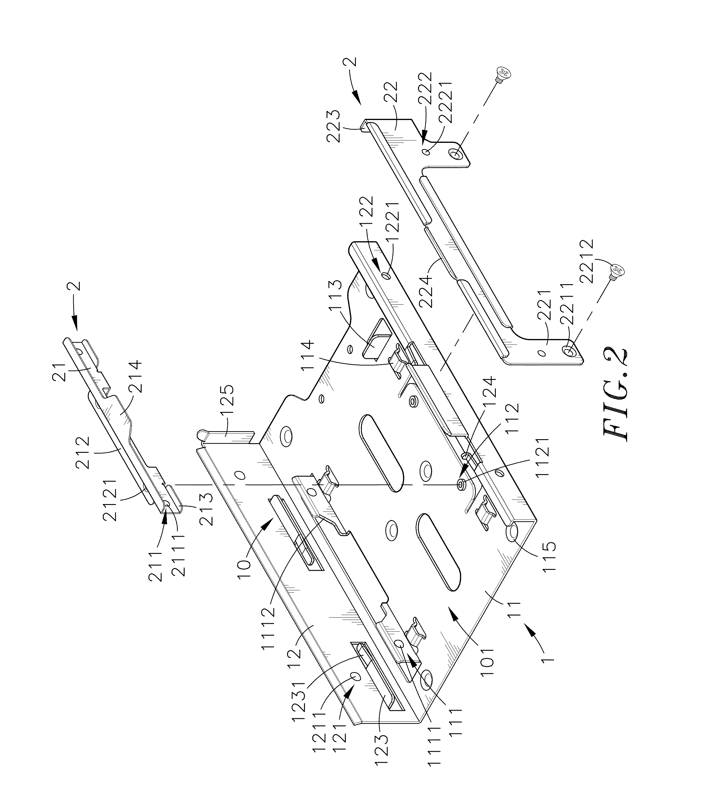
[0021]Referring to FIGS. 1-6, an in-box quick release access device mounting structure adapted for holding an access device 3 in accordance with the present invention is shown. The in-box quick release access device mounting structure comprises a holder shell 1 and a retaining mechanism 2.

[0022]The holder shell 1 is made of a rigid material, for example, galvanized steel, in one piece. The holder shell 1 comprises a bottom panel 11, two side panels 12 vertically upwardly extended from two opposite lateral sides of the bottom panel 11, an accommodation chamber 10 surrounded by the bottom panel 11 and the two side panels 12, a first positioning member 111 vertically upwardly extended from the bottom panel 11 adjacent to one (the left) side panel 12 in a parallel relationship and having an opening 1112 on the middle and two raised portions 1111 located at an outer wall thereof at two opposite lateral sides relative to the opening 1112, a first locating member 112 obliquely extended fro...


PUM


Abstract

An in-box quick release access device mounting structure includes a rigid holder shell including an accommodation chamber surrounded by a bottom panel and two opposite side panels thereof, a first positioning member and a first locating member located at the bottom panel and defining a mounting space therebetween, a second positioning member and a second locating member respectively located at the two side panels, and a retaining mechanism including a first retaining plate fastened to the first positioning member and adapted for detachably securing a small access device in the mounting space and a second retaining plate fastened to the second locating member and adapted for detachably securing a large access device in the accommodation chamber.

Description

BACKGROUND OF THE INVENTION[0001]1. Field of the Invention[0002]The present invention relates to access device mounting technology and more particularly, to an in-box quick release access device mounting structure, which comprises a holder shell defining therein an accommodation chamber for accommodating a large access device and a mounting space in the accommodation chamber for accommodating a small access device, and a retaining mechanism that comprises a first retaining plate mounted in the holder shell for detachably securing a small access device in the mounting space and a second retaining plate mounted at one lateral side of the holder shell for detachably securing a large access device in the accommodation chamber.[0003]2. Description of the Related Art[0004]With the continuous development of computer technology, computer hardware equipments are created having the characteristics of versatile functions, high operating speed and small size for multipurpose applications. In a ...

Claims


Application Information

Patent Timeline
IPC IPC(8): H05K5/02
CPCG06F1/18G11B33/125G06F1/1658G06F1/187G11B33/124G06F1/181
Inventor HU, TSENG-HSUN
Owner CHENBRO MICOM
Why Eureka
Try Eureka