
Refrigerator

a technology of refrigerators and water storage containers, which is applied in the field of refrigerators, can solve the problems of difficult water injection to inconvenient detachment of difficulty in mounting the water supply container, etc., and achieves convenient mounting of the water storage container, simple structure, and easy injection

Active Publication Date: 2013-05-30
SAMSUNG ELECTRONICS CO LTD
View PDF6 Cites 9 Cited by
  • Summary
  • Abstract
  • Description
  • Claims
  • Application Information

AI Technical Summary

Benefits of technology

The present disclosure provides a refrigerator with a water supply system that can supply water to an ice making apparatus or a dispenser from a water storage vessel instead of from an external source. This enhances the convenience of mounting the water storage vessel and makes the refrigerator more space-efficient and aesthetically pleasing. The water supply system includes a compact and aesthetically pleasing water storage vessel, a pump, and a valve that are all located inside the refrigerator housing. The system also includes a passage changing apparatus that simplifies the connection between the water storage vessel and the ice making apparatus or dispenser. The water storage vessel is designed for easy mounting, and water can be easily injected into it even when it is mounted. The pump and valve are assembled with a simple structure and enhanced space utilization and aesthetic appearance.

Problems solved by technology

However, in accordance with the publication above, in a case when the water supplying container is to be mounted to the container connecting part, a portion of the second passage is needed to be disposed at an inside the water supplying container through the entry of the water supplying container, and thus, mounting of the water supplying container may not be easily performed.
In addition, since the second passage passes through an injection hole of the water supplying container, the injection of the water to the water supplying container may be difficult in a state when the water supplying container is mounted at the container connecting part.
Accordingly, in a case when the water is needed to be injected to the water supplying container, it is necessary to inconveniently detach the water supplying container from the container connecting part prior to injecting water.

Method used


Image

  • Refrigerator
  • Refrigerator
  • Refrigerator

Examples


first embodiment

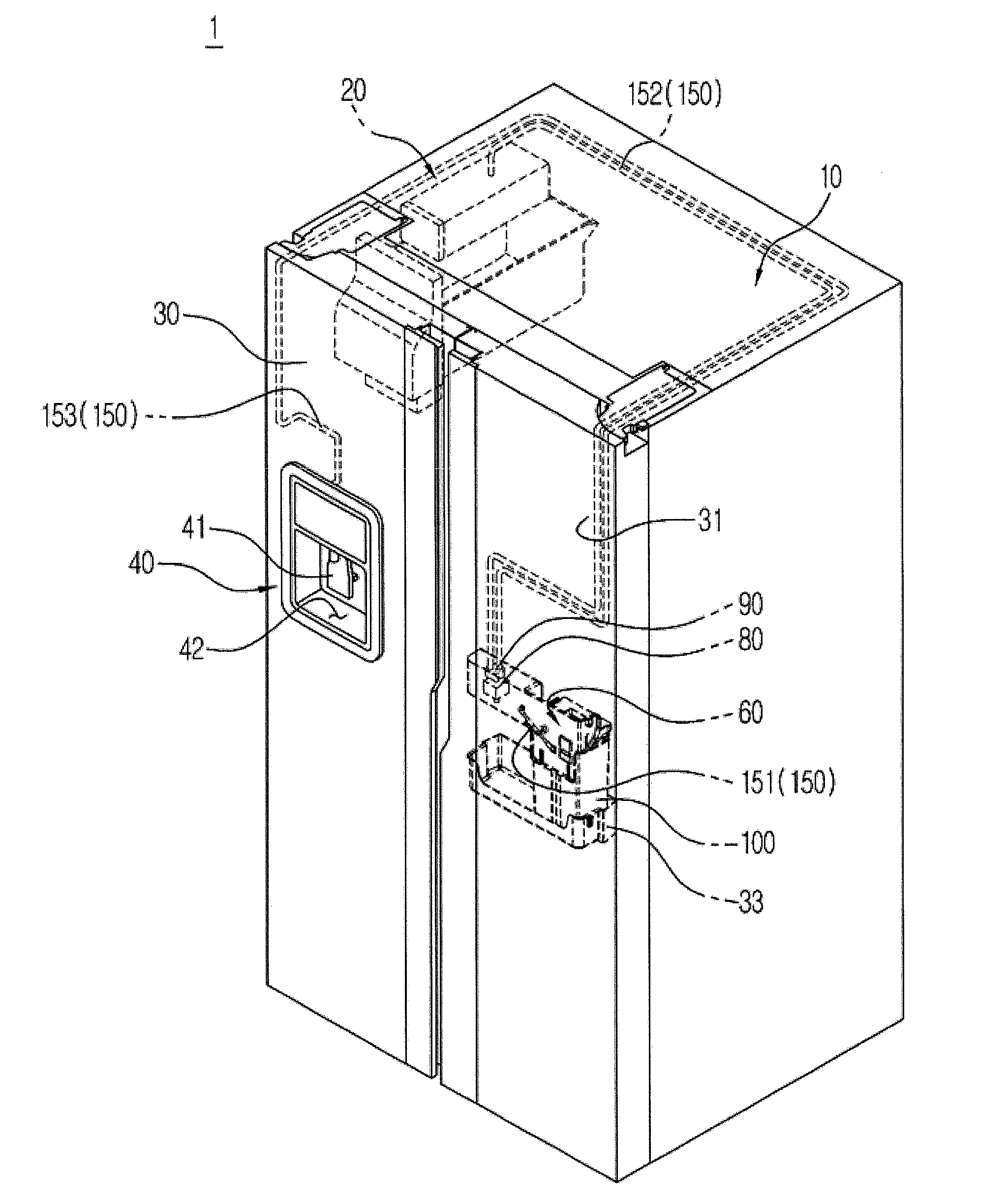
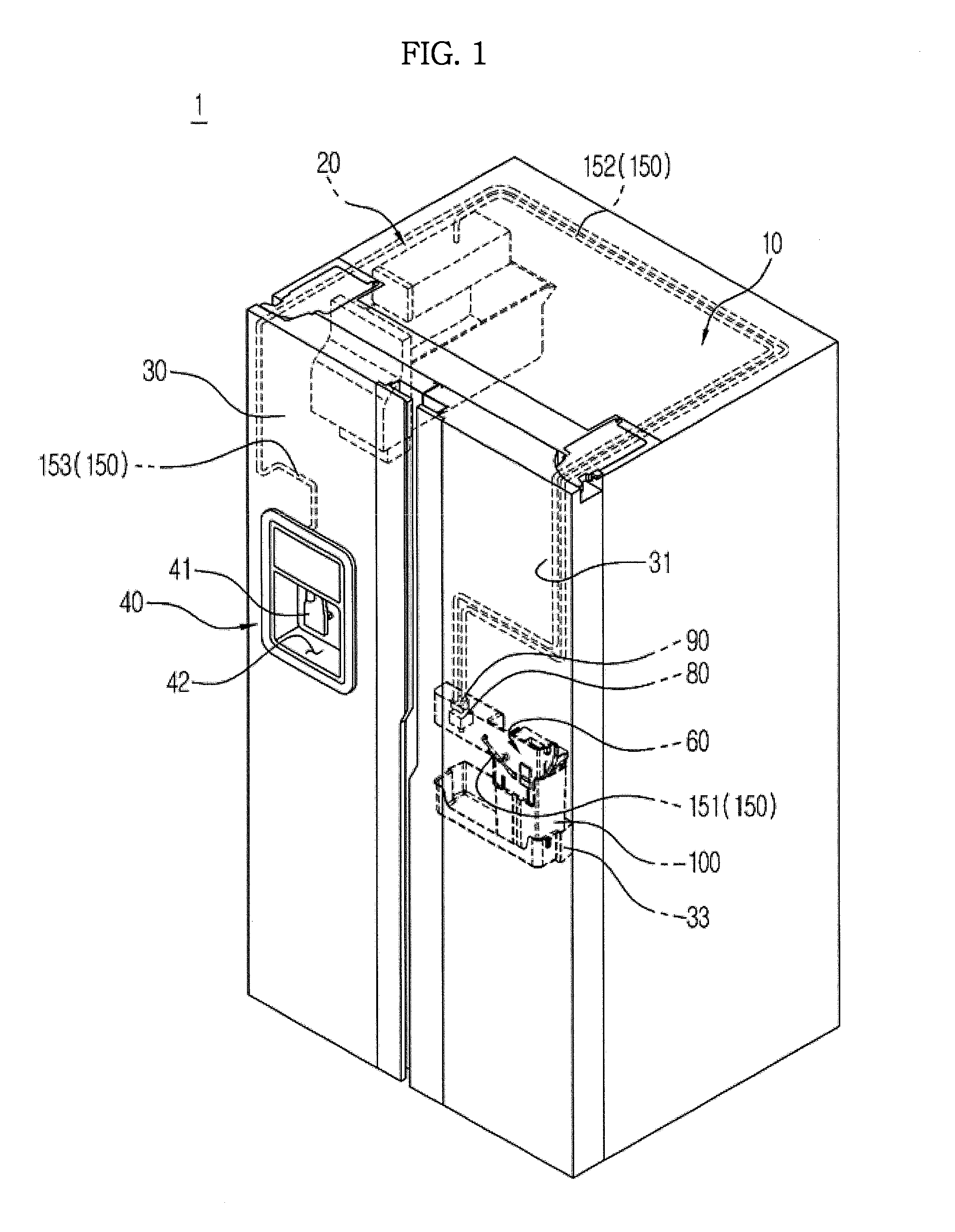
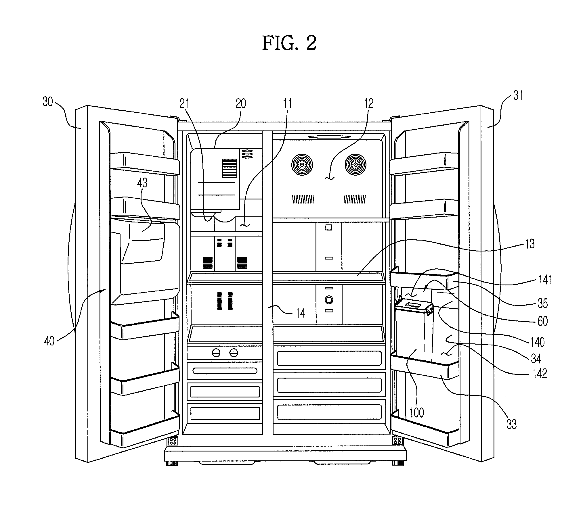
[0049]FIG. 1 is a schematic view of a water supply system of a refrigerator in accordance with the present disclosure. FIG. 2 is a frontal view of the refrigerator of FIG. 1.

[0050]As illustrated on FIGS. 1 to 2, a refrigerator 1 according to a first embodiment of the present disclosure includes a body 10 forming an exterior, storage compartments 11 and 12 provided at the inside the body 10 to store foods therein, and a cooling apparatus (not shown) to supply cool air to the storage compartments 11 and 12 to keep the foods fresh stored therein.

[0051]The storage compartments 11 and 12 may be divided by a middle wall 14 into the storage compartment 11 on the left and the storage compartment 12 on the right. The storage compartment 11 on the left may be used as a freezing compartment to keep the foods frozen, and the storage compartment 12 in the right may be used as a refrigerating compartment to keep the foods refrigerated.

[0052]The storage compartments 11 and 12 are provided thereon ...

third embodiment

[0062]Thus, the valve 90 may be a 3-way valve having three entry / exit holes. However, according to the present disclosure which will be described later, the passage conversion may be achieved by using four check valves instead of the 3-way valve. Additional explanations will be provided later.

[0063]The water storage vessel 100 may be detachably mounted at the bracket unit 60 that is installed on a rear surface 34 of the door 31, and the water storage vessel 100 mounted at the bracket unit 60 may be supported by a door guard 33 provided at the rear surface 34 of the door 31. The bracket unit 60 may be injection-molded with plastic or steel material, and may be fixedly installed by a fastening member on the rear surface 34 of the door 31.

[0064]Although will be explained, through the structure as the above, the ice making apparatus 20 or the dispenser 40 of the refrigerator 1 according to the embodiment of the present disclosure, instead of being supplied with water from an outside wat...

second embodiment

[0093]FIG. 10 is a view illustrating a bracket unit in a state that a water storage vessel lever of a refrigerator in accordance with the present disclosure is open. FIG. 11 is a view illustrating a bracket unit in a state that a water storage vessel lever of the refrigerator of FIG. 10 is closed. FIG. 12 is a side cross sectional view illustrating a bracket unit in a state that the water storage vessel lever of the refrigerator of FIG. 10 is open. FIG. 13 is a side cross sectional view illustrating a bracket unit in a state that the water storage vessel lever of the refrigerator of FIG. 10 is open.

[0094]By referring to FIGS. 10 to 13, a refrigerator according to the second embodiment of the present disclosure will be explained. With respect to the same structure as that of the first embodiment of the present disclosure, the same reference numerals will be used to designate the same structures hereafter, while the explanations of such may be omitted.

[0095]According to the second emb...


PUM


Abstract

A refrigerator includes a water storage vessel configured to be mounted to the door of the refrigerator, a supply passage configured to connect the storage space of the water storage vessel to an ice making apparatus and dispenser to supply the water in the water storage vessel to the ice making apparatus and the dispenser, a valve installed at an intersection of the supply passage and configured to perform a passage conversion, and a pump configured to pump the water in the water storage vessel so that the water flows to the supply passage, wherein the water storage vessel is provided with a water storage vessel lever capable of changing the position of at least one portion of the supply passage so that the at least one portion of the supply passage is connected to / disconnected from a remaining portion of the supply passage.

Description

CROSS-REFERENCE TO RELATED APPLICATIONS[0001]This application claims the benefit of Korean Patent Application No. 2011-0126253, filed on Nov. 29, 2011 in the Korean Intellectual Property Office, the disclosure of which is incorporated herein by reference.BACKGROUND[0002]1. Field[0003]Embodiments of the present disclosure relate to a refrigerator having an ice making apparatus or a dispenser, and more particularly, to a refrigerator configured to be supplied with water from a water storage vessel that is detachably mounted to the refrigerator instead of receiving water while connected to a faucet from an outside water supply source.[0004]2. Description of the Related Art[0005]In general, a refrigerator is an apparatus provided with a storage compartment therein to store foods and a cool air supply device to supply cool air to the storage compartment to keep food fresh through a cooling cycle.[0006]The refrigerator as such is in the ever increasing trend of becoming larger in size fol...

Claims


Application Information

Patent Timeline
Patent Type & Authority Applications(United States)
IPC IPC(8): F25C1/00F25D11/00
CPCF25C1/00F25D11/00F25D2323/122F25C2400/10F25C2400/14F25D23/126F25C1/24F25D19/00F25D25/00
Inventor PARK, SANG MIN
Owner SAMSUNG ELECTRONICS CO LTD
Learn More