Retainer for heat sink

Inactive Publication Date: 2005-10-27
HON HAI PRECISION IND CO LTD +1
View PDF9 Cites 10 Cited by
  • Summary
  • Abstract
  • Description
  • Claims
  • Application Information

AI Technical Summary

Benefits of technology

[0004] Accordingly, an object of the present invention is to provide a retainer which can conve

Problems solved by technology

As a result, large force is needed in operation.
Furthermore, the legs 94 of the clips 9

Method used


Image

  • Retainer for heat sink
  • Retainer for heat sink
  • Retainer for heat sink

Examples


Embodiment Construction

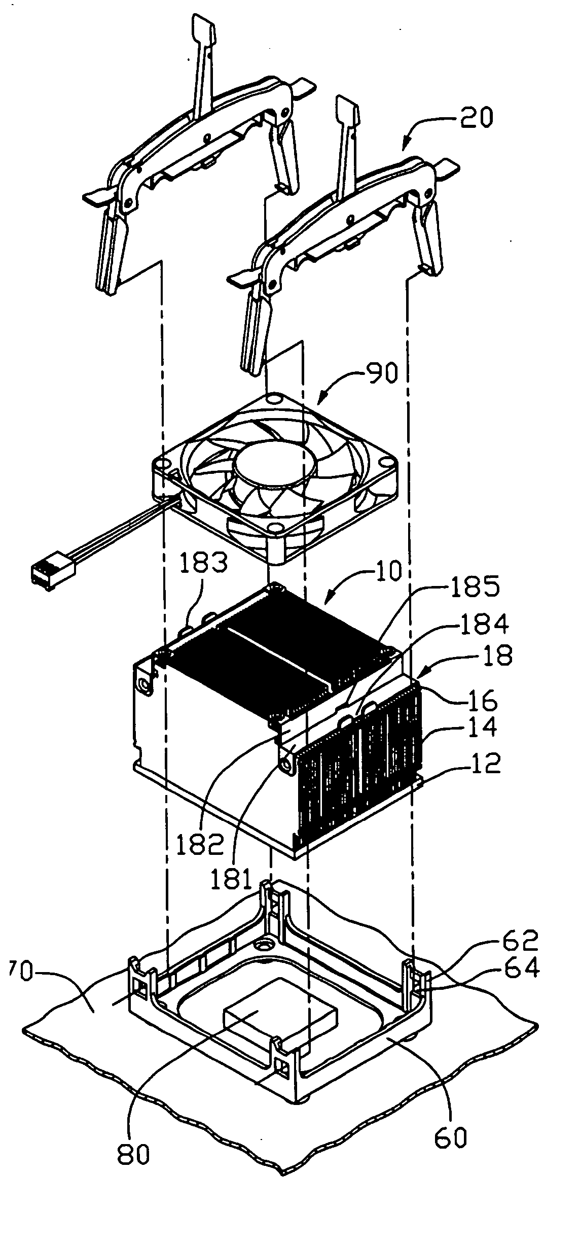
[0012] Referring to FIG. 1, a retainer for mounting a heat sink 10 on a CPU 80 mounted on a printed circuit board 70 is shown. The retainer comprises two clip members 20 and a retention module 60. The heat sink 10 comprises a base 12 for contacting the CPU 80, and a plurality of parallel fins 14 extending upwardly from the base 12. Two shoulders 16 are formed at opposite sides of the fins 14. A pair of supporting members 18 with a plate configuration is attached on the shoulders 16. Each supporting member 18 has a horizontal portion 181 and a vertical portion 182. The outer side edge of each horizontal portion 181 forms a tab 183 defining a cutout 184 therein. The vertical portion 182 defines a cutout 185 aligned with the corresponding cutout 184. Four mounting portions (not labeled) are formed at four corners of the vertical portion 182 for mounting a fan 90 thereon.

[0013] The retention module 60 is mounted on the printed circuit board 70 around the CPU 80. The retention module 60...


PUM


Abstract

A retainer includes a retention module surrounding a heat sink and two clip members for cooperating with the retention module to retain the heat sink. Each clip member includes a strap resting on the heat sink and a pair of legs located at opposite ends of the strap and engagable with the retention module. The legs are pivotably attached to opposite ends of the strap. Friction between the legs and the strap is capable of holding the legs at any positions between released positions at which the legs are free from the retention module and engaged positions at which the legs are engaged with the retention module.

Description

TECHNICAL FIELD [0001] The present invention relates to a retainer, and particularly to a retainer for conveniently mount a heat sink to a heat generating unit. BACKGROUND [0002] As computer technology continues to advance, electronic components such as central processing units (CPUs) of computers are made to provide faster operational speeds and greater functional capabilities. When a CPU operates at a high speed in a computer enclosure, its temperature can increase greatly. It is desirable to dissipate the generated heat quickly, for example, by using a heat sink attached to the CPU in the enclosure. This allows the CPU and other high-performance electronic components in the enclosure to function within their normal operating temperature ranges, thereby assuring the CPU quality of data management, storage and transfer. Oftentimes, a retainer is required for mounting the heat sink to the CPU. [0003] One conventional retainer developed to mount a heat sink to a CPU is illustrated in...

Claims


Application Information

Patent Timeline
IPC IPC(8): G06F1/20H01L23/40H01L23/467H05K7/20
CPCH01L23/4093H01L23/467Y10T24/44026H01L2924/0002H01L2924/00
Inventor LI, DONG-YUNSHI, HONG-BOLI, MIN
Owner HON HAI PRECISION IND CO LTD
Why Eureka
Try Eureka