Vehicle floor system

a floor system and vehicle technology, applied in the field of vehicle floor systems, can solve the problems of lack of structural properties, lack of plywood, chemical and physical limitations,

Inactive Publication Date: 2016-06-23
VIXEN COMPOSITES LLC
View PDF1 Cites 7 Cited by
  • Summary
  • Abstract
  • Description
  • Claims
  • Application Information

AI Technical Summary

Benefits of technology

[0003]The present disclosure describes an improved flooring structure where a reinforcing member provides additional rigidity along with a convenient place to mount other items. Reinforcing members are spaced according to the desired strength of the overall structure and possible mounting points. A core material provides strength to resist crushing of the structure and a smooth top and bottom surface are bonded to the core and reinforcing members using an epoxy or other adhesive. The core material can also provide insulating properties. The flooring structure is manufactured using a pultrusion process for creating a continuous sheet. The pultrusion process starts by unwinding upper and lower continuous rolls of material, such as filament mat or mesh. The material is then impregnated by drawing it through a bath of resin or other heat-curable epoxy. Core and reinforcing members are placed between the impregnated material and compressed and heated by a pultrusion die. The compression ensures contact between the layers, and the heat cures the epoxy resin. Located further down in the process is a pulling station where tank treads pull the materials through the die. Finally, the cured assembly is separated into individual sheets at a cutoff station.

Problems solved by technology

Honey-comb insulation is available but lacks sufficient structural properties to act as a supporting floor for a vehicle.
Currently available flooring structures use a piece of laminated plywood as one layer to improve rigidity, but plywood has chemical and physical limitations.

Method used


Image

  • Vehicle floor system
  • Vehicle floor system
  • Vehicle floor system

Examples


Embodiment Construction

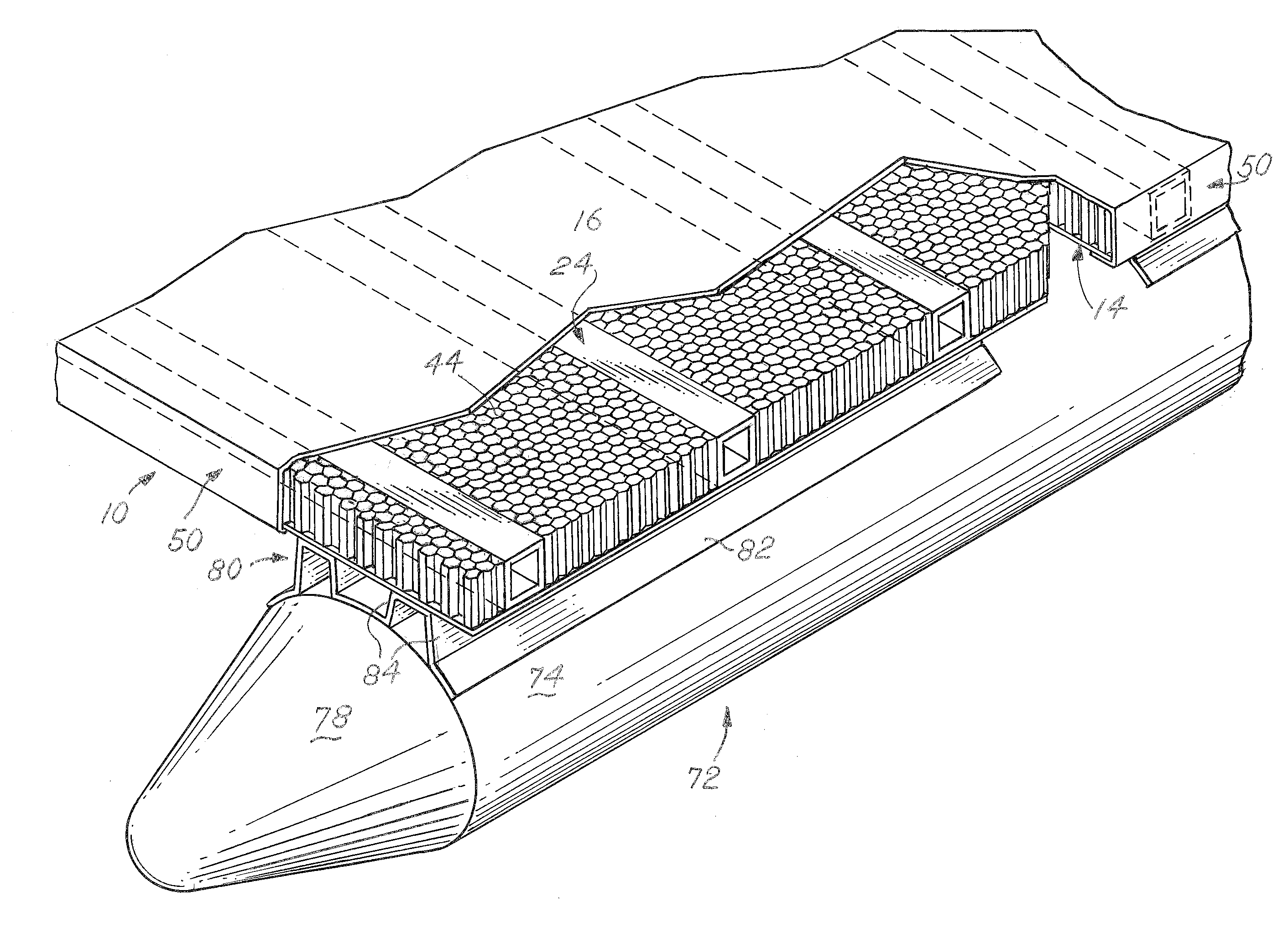
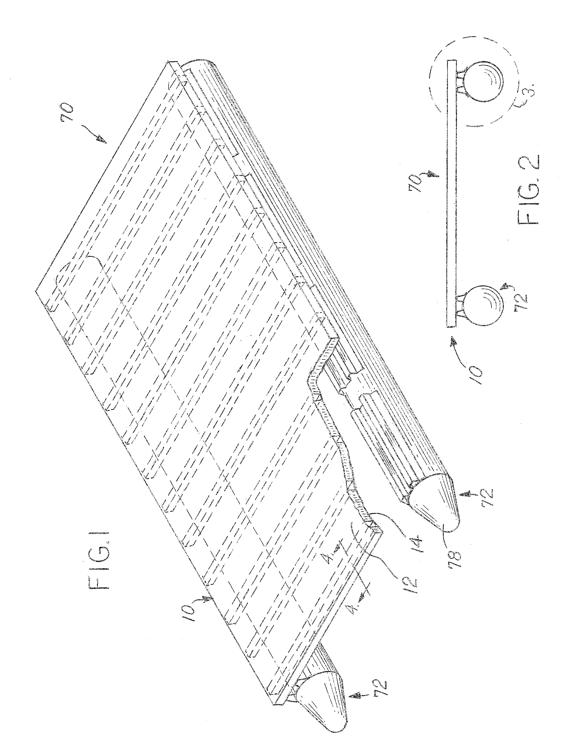
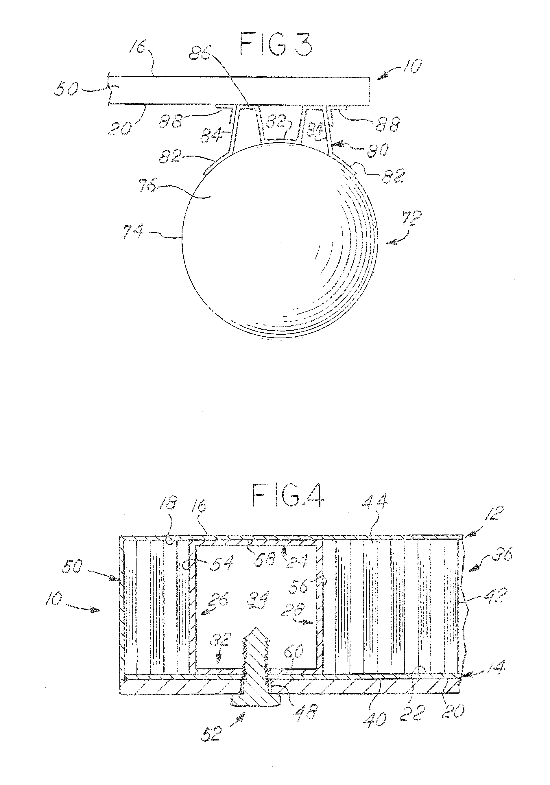
[0013]A flooring structure 10 for a pontoon boat 70 or other device has an upper wall 12 and a lower wall 14. The upper wall 12 and lower wall 14 are formed from a rigid sheet of fiberglass or equivalent. The upper and lower walls 12, 14 in the embodiment shown are fiberglass sheets that have been wetted with epoxy resin. Both upper and lower walls 12, 14 resist stretching or compressing and are an integral part of the strength of the structure 10. The upper wall 12 has an exposed surface 16 and an internal surface 18. The lower wall 14 has an equivalent exposed surface 20 and an internal surface 22. The flooring structure 10 is attached to individual pontoons 72 to form both a flooring surface and flooring structure. The specification is directed towards a floor in a pontoon boat 70, but it is contemplated that the structure 10 is used for walls, roofing, or other purposes where a rigid flat sheet is needed.

[0014]Located between the upper wall 12 and lower wall 14 are two different...


PUM

PropertyMeasurementUnit
thicknessaaaaaaaaaa
compressed thicknessaaaaaaaaaa
wettingaaaaaaaaaa

Abstract

A vehicle floor system and method of manufacturing is provided having a lower layer, an upper layer, and a series of core sections interrupted by transverse structural members. The layers are impregnated with a heat-curable adhesive. The core sections and transverse structural members are compressed with the impregnated layers and cured to form a continuous sheet. The method of manufacturing the floor system where the upper layer is unwound and impregnated with the adhesive, the lower layer is unwound and impregnated with the adhesive. The core sections are placed between the layers and transverse members are placed between. A curing station is provided where the layers are compressed and adhesive heat-cured to create the continuous sheet. The continuous sheet is then separated by a saw.

Description

CROSS REFERENCE TO RELATED APPLICATIONS[0001]This application claims the benefit of U.S. Provisional Application No. 62 / 095,501, filed Dec. 22, 2014, the disclosures of which are hereby incorporated by reference.BACKGROUND OF THE INVENTION[0002]Vehicles, especially pontoon boats or recreational vehicles are frequently built on a flat surface. The flat surface is used to mount walls, seats, and the like, but is not a structural member. The flat surface merely sits on a frame. Further, insulation has to be added to keep heat from escaping. Honey-comb insulation is available but lacks sufficient structural properties to act as a supporting floor for a vehicle. Currently available flooring structures use a piece of laminated plywood as one layer to improve rigidity, but plywood has chemical and physical limitations. The methods for making these involve vacuum bags and other discrete processes that create individual discrete pieces, creating waste, gaps between the core and the structura...

Claims


Application Information

Patent Timeline
Patent Type & Authority Applications(United States)
IPC IPC(8): B32B3/12B29C70/52B32B7/12B29C65/00B29C35/02B32B3/08B63B5/24B29C65/48
CPCB32B3/12B32B2605/12B29C70/521B29C65/48B29C66/721B29C66/45B29C35/0222B32B3/08B32B7/12B29K2063/00B29K2105/08B29K2309/08B29K2995/0089B29L2007/008B29L2009/00B29L2031/3017B32B2250/03B63B5/24B29D99/0021B32B5/02B32B5/26B32B15/14B32B21/10B32B3/02B32B3/18B32B3/20B32B2260/021B32B2260/046B32B2262/101B32B2307/546B32B2307/734B32B2605/08B32B2607/00B32B2266/00
Inventor MANDERFELD, RAYMOND M.FROST, GORDON
Owner VIXEN COMPOSITES LLC
Why Eureka
Try Eureka