

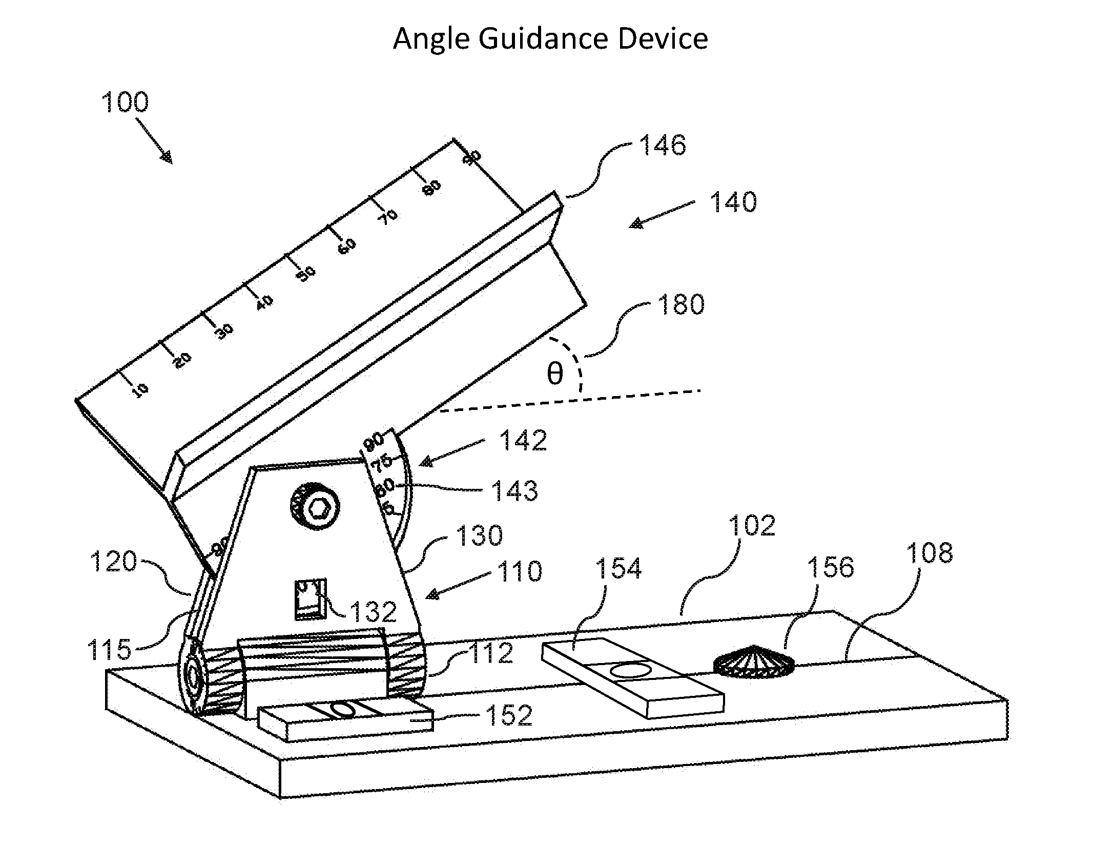
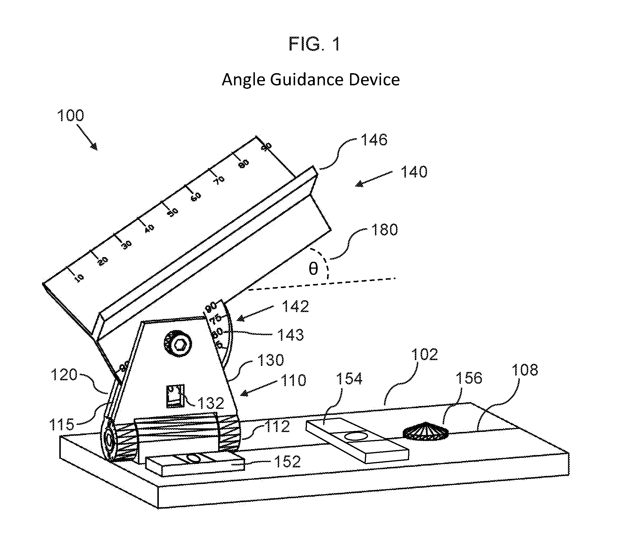
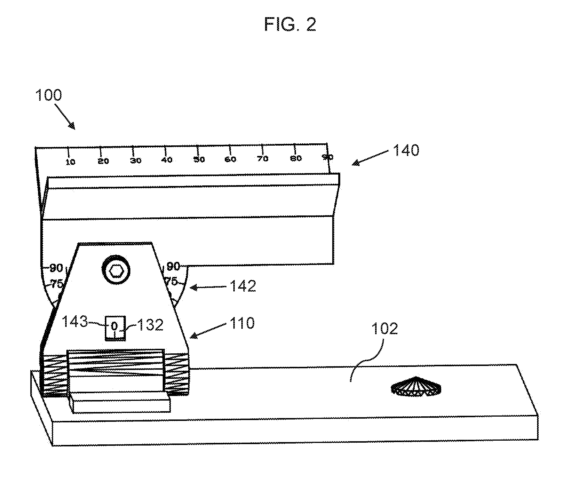
Angle-guidance device and method for CT guided drainage and biopsy procedures
a technology of guided needle drainage and guide device, which is applied in the field of ct guided needle drainage and biopsy procedures, can solve the problems of trial-and-error technique, inability to guide the radiologist to choose the correct angle for the biopsy, and inability to provide accurate access methods in vertical trajectory at 90-degree angles
- Summary
- Abstract
- Description
- Claims
- Application Information
AI Technical Summary
Benefits of technology
Problems solved by technology
Method used
Image

Examples
Embodiment Construction
[0036]Before describing the invention in detail, it should be observed that the present invention resides primarily in a novel and non-obvious combination of elements and process steps. So as not to obscure the disclosure with details that will readily be apparent to those skilled in the art, certain conventional elements and steps have been presented with lesser detail, while the drawings and specification describe in greater detail other elements and steps pertinent to understanding the invention.
[0037]The following embodiments are not intended to define limits as to the structure or method of the invention, but only to provide exemplary constructions. The embodiments are permissive rather than mandatory and illustrative rather than exhaustive.
[0038]In the following, we describe the structure of an embodiment of an angle-guidance device 100 with reference to FIG. 1, in such manner that like reference numerals refer to like components throughout; a convention that we shall employ f...
PUM
 Abstract
Description
Claims
Application Information