

Direct-current power transmission power conversion device and direct-current power transmission power conversion method
- Summary
- Abstract
- Description
- Claims
- Application Information
AI Technical Summary
Benefits of technology
Problems solved by technology
Method used
Image

Examples
embodiment 1
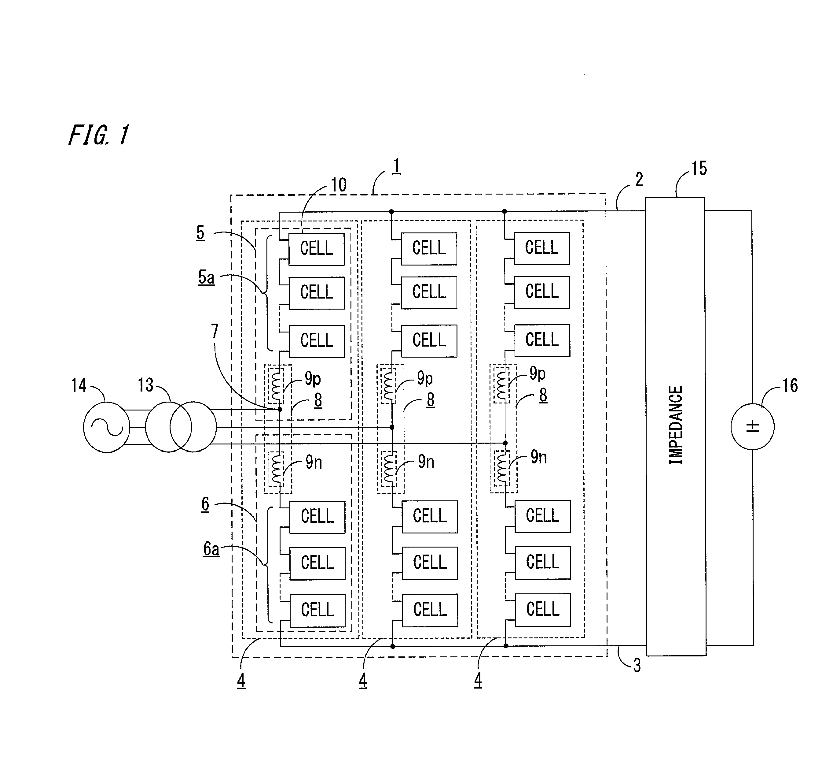
[0034]FIG. 1 is a schematic configuration diagram of a DC power transmission power conversion device according to embodiment 1 of the present invention.
[0035]The DC power transmission power conversion device of embodiment 1 includes a power converter 1 as a main circuit, and a control device 20 described later for controlling the power converter 1.
[0036]The power converter 1 performs power conversion between plural-phase AC (here, particularly, three-phase AC) and DC. The AC side of the power converter 1 is connected via an interconnection transformer 13 to an AC power supply 14 which is an AC grid, and the DC side is connected via an impedance 15 to a DC power supply 16. As the DC power supply 16 in this case, another power conversion device for performing DC output is applied. The connection to the AC power supply 14 may be made via an interconnection reactor instead of using the interconnection transformer 13 shown in FIG. 1.
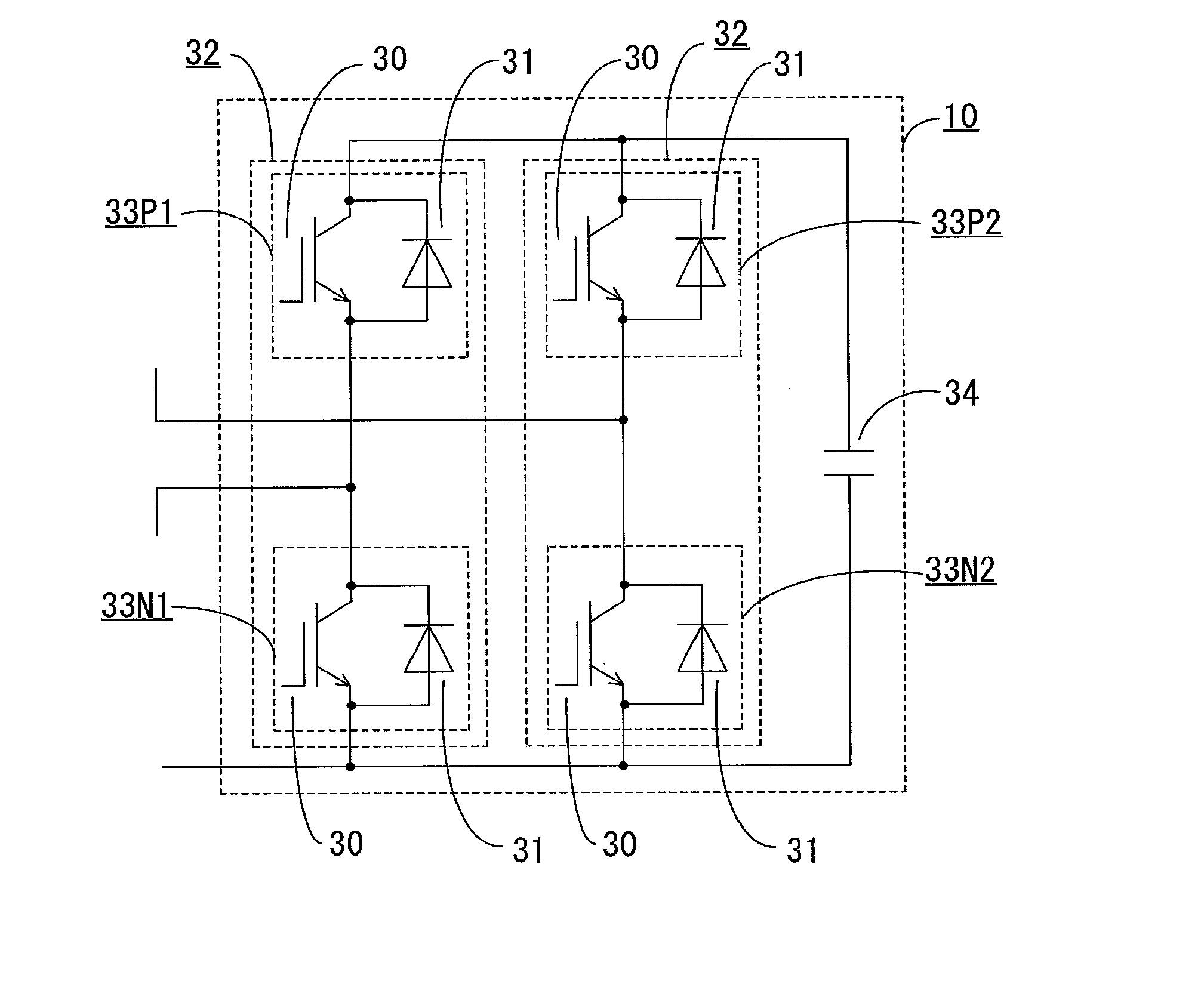
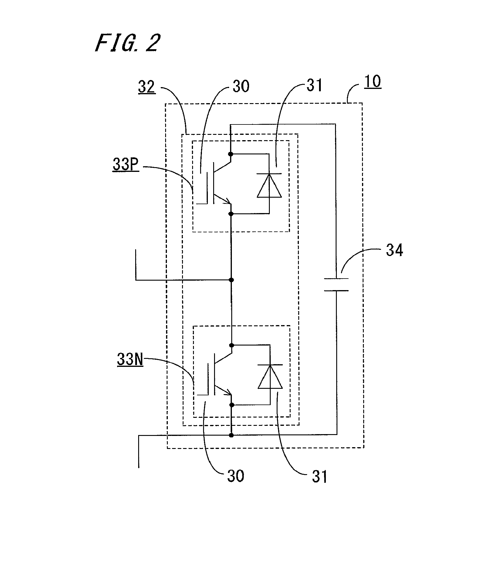
[0037]In each phase of the power converter 1, a positiv...
embodiment 2
[0087]FIG. 5 is a block diagram showing a configuration example of a control device of a DC power transmission power conversion device according to embodiment 2 of the present invention.
[0088]In the present embodiment 2, the configuration of the power converter 1 is the same as that in the above embodiment 1 shown in FIG. 1, but the configuration of the control device 20 is different from that in the above embodiment 1.
[0089]In the present embodiment 2, as in embodiment 1, in order to control the capacitor voltage Vcap of each converter cell 10, on the basis of information about the detected capacitor voltages Vcap of all the converter cells 10 for each phase, the capacitor voltage control unit 24 generates current command values (active current command value ipref, positive arm current command value ip+ref, negative arm current command value ip−ref) and gives them to the current control unit 25.
[0090]Particularly, the active current command value ipref outputted from the capacitor ...
embodiment 3
[0117]FIG. 6 is a block diagram showing a configuration example of a control device of a DC power transmission power conversion device according to embodiment 3 of the present invention.
[0118]In the present embodiment 3, the configuration of the power converter 1 is the same as that in the above embodiment 1 shown in FIG. 1, but the configuration of the control device 20 is slightly different from those in the above embodiments 1 and 2.
[0119]In the present embodiment 3, the configurations of the DC voltage control unit 21 and the current control unit 25 are the same as those in embodiment 1, and the configurations of the capacitor voltage control unit 24, the DC current calculation unit 28, the adders 23 and 26, and the PWM control unit 27 are the same as those in embodiment 2.
[0120]Unlike the case of embodiment 2, the DC current control unit 22, as well as receiving the detected DC current idc and the DC current excessive component Δidc calculated by the DC current calculation unit...
PUM
 Abstract
Description
Claims
Application Information