Base body of electric transmission tower using micropile

a technology of electric transmission tower and base body, which is applied in the direction of towers, buildings, constructions, etc., can solve the problems of long construction period and difficult transportation of materials and equipment, and achieve the effect of reducing environmental damage, reducing time, and costing manpower for installing electric transmission towers

Active Publication Date: 2017-07-06
KOREA ELECTRIC POWER CORP
View PDF1 Cites 2 Cited by
  • Summary
  • Abstract
  • Description
  • Claims
  • Application Information

AI Technical Summary

Benefits of technology

[0020]In accordance with the base body of an electric transmission tower using a micropile of the present disclosure, a foundation member is assembled using a plurality of foundations so that installation may be easily performed, and a period of time, costs, and manpower required for installing an electric transmission tower and environmental damage may be reduced.
[0021]Also, in accordance with the present disclosure, the foundation member is compressed using a micropile such that a tensile force, which is generated when a wind load and the like is applied to the electric transmission tower, may be counterbalanced, thereby improving durability of the foundation member.
[0022]Also, in accordance with the present disclosure, a pile cap part is provided so that corrosion of a pile part may be prevented and a performance of a device may be maintained.

Problems solved by technology

However, since a location at which an electric transmission tower is installed is a ridge of mountain, a steeply sloped land, or the like, there are problems in that transportation of materials and equipment is very difficult, environmental damage occurs due to a large scale foundation construction, and a long construction period is required.

Method used


Image

  • Base body of electric transmission tower using micropile
  • Base body of electric transmission tower using micropile
  • Base body of electric transmission tower using micropile

Examples


Embodiment Construction

[0040]Hereinafter, embodiments of a base body of an electric transmission tower using a micropile according to the present disclosure will be described with reference to the accompanying drawings. In the course of the description, a thickness of a line, a size of a component, or the like which are shown in the drawings may be exaggerated for clarity and convenience of a description.

[0041]Also, all terms used hereinafter are selected in consideration of a function in an embodiment, and meanings thereof may be different according to the intent of a user and an operator or custom. Therefore, the definitions of these terms used in the following embodiments should be based on the content disclosed herein.

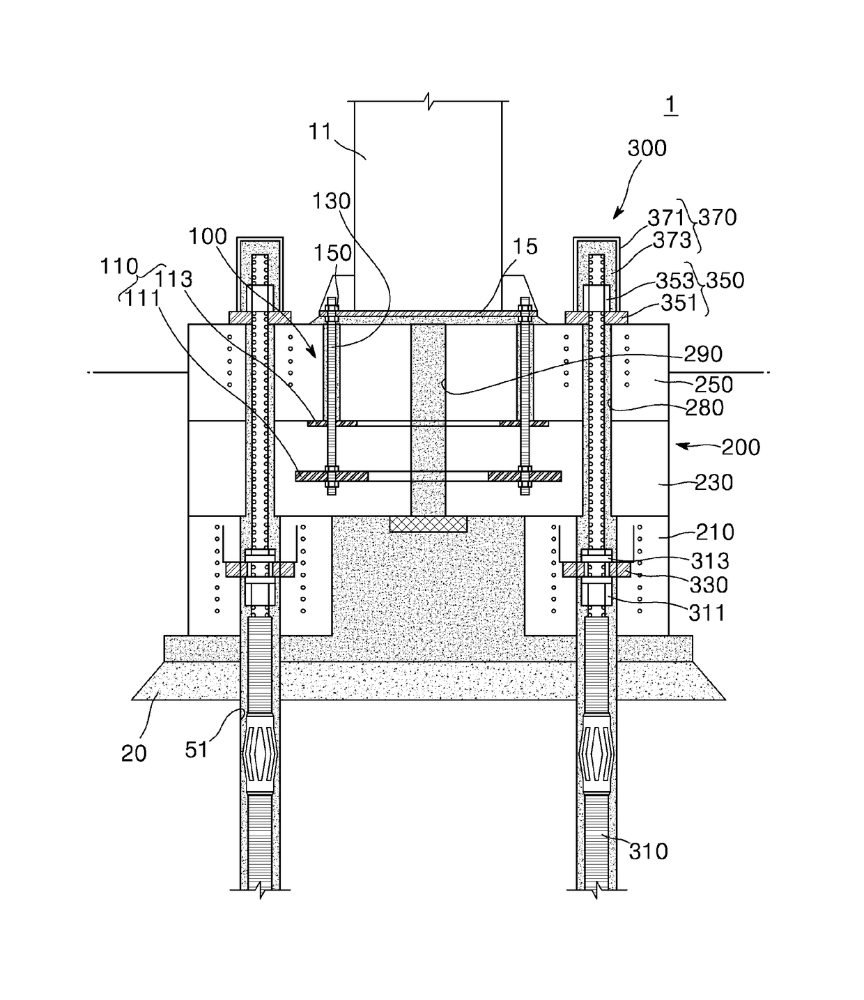
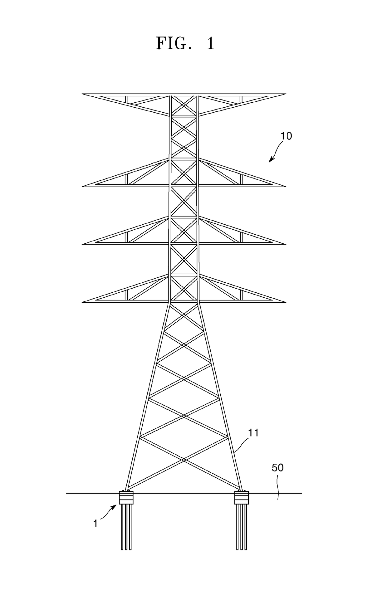
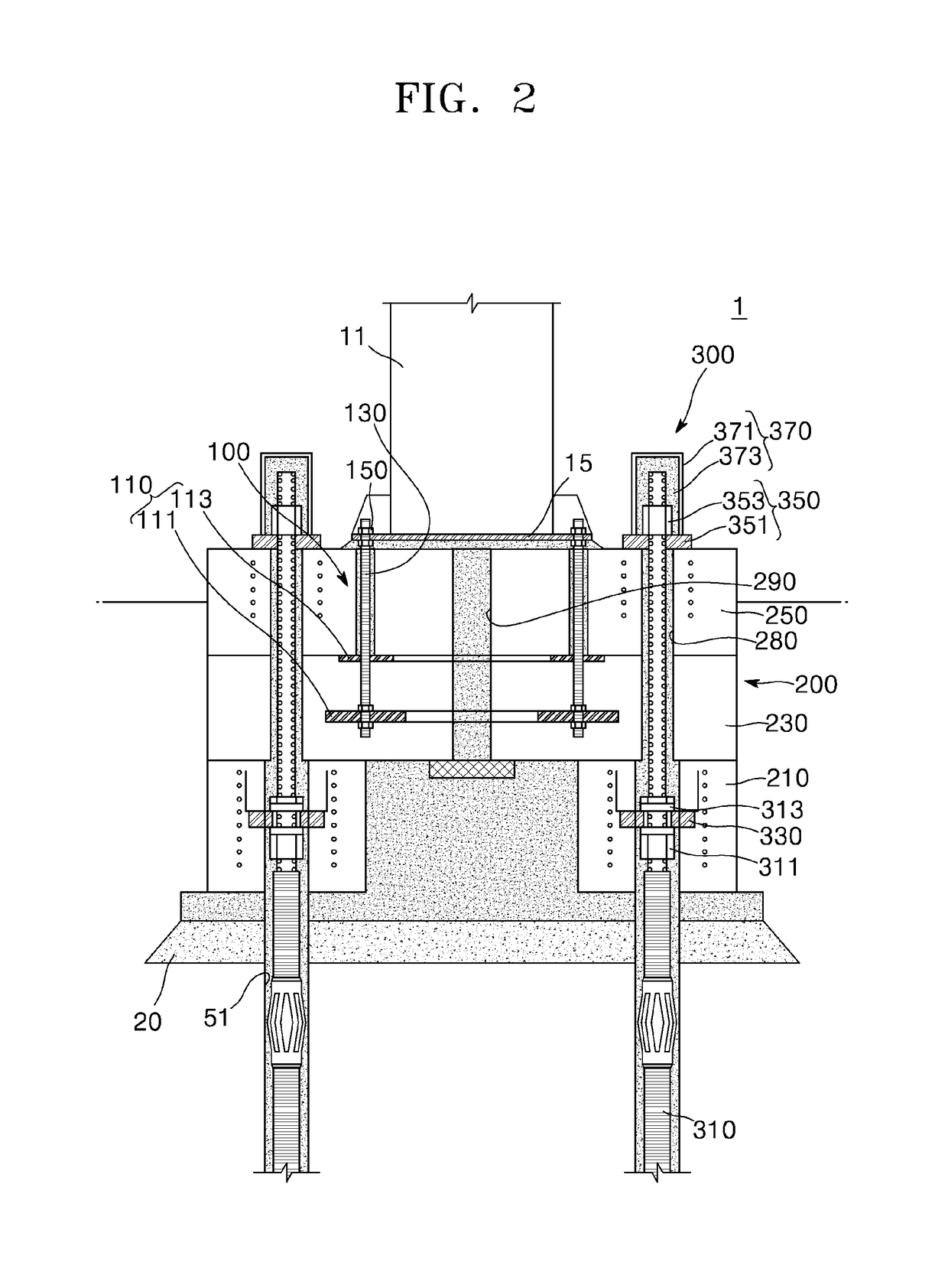
[0042]FIG. 1 is a diagram illustrating a state in which a base body of an electric transmission tower using a micropile is installed according to one embodiment of the present disclosure, FIG. 2 is a diagram illustrating a cross section of a base body of an electric transmission tower us...


PUM


Abstract

Disclosed is a base body of an electric transmission tower using a micropile. The base body of the electric transmission tower using the micropile includes an anchor member coupled to a main pole member of the electric transmission tower, a foundation member coupled to the anchor member and including a plurality of foundations, and the micropile configured to fix the foundation member to the ground and compress the foundation member.

Description

TECHNICAL FIELD[0001]The present disclosure relates to a base body of an electric transmission tower using a micropile, and more particularly, to a base body of an electric transmission tower using a micropile, which is capable of reducing a construction time, costs and environmental damage and improving durability of a device by being applied with foundation members including a plurality of foundation.BACKGROUND ART[0002]A conventional electric transmission tower is a truss shaped steel structure constructed from the ground to a height of several tens of meters and is configured with a heavy material having a dead load in a range of several tens of tons to several hundreds of tons in order to construct electric transmission lines. Such an electric transmission tower typically has four main pole members which are disposed in square, and a lower end of each of the four main pole members is fixed to the ground by means of a concrete base body.[0003]To construct electric transmission t...

Claims


Application Information

Patent Timeline
Patent Type & Authority Applications(United States)
IPC IPC(8): E02D27/42E02D5/22E04H12/22
CPCE02D27/42E04H12/2238E02D5/22E04H12/10E02D2250/003E02D2300/0026E02D11/00E02D2300/0025E02D2300/0021E02D2300/002
Inventor KIM, DAE HONGPYO, WON SAMKIM, JANG GOONLEE, DAE SOO
Owner KOREA ELECTRIC POWER CORP
Why Eureka
Try Eureka