Optical dynamic burst switch

a dynamic burst switch and optical technology, applied in the field of optical dynamic burst switch, can solve the problems of requiring a certain time period, requiring a large amount of time for this type of setting procedure, and inefficient burst data transfer by individual ip packet units, so as to reduce labor and time period, achieve efficient network resources, and perform burst data transfer reliably

Inactive Publication Date: 2007-04-03
NIPPON TELEGRAPH & TELEPHONE CORP
View PDF34 Cites 3 Cited by
  • Summary
  • Abstract
  • Description
  • Claims
  • Application Information

AI Technical Summary

Benefits of technology

[0114]In other words, with the present invention, upon a path such as a cut through path by wavelength path over which optical signal data is being transferred just as it is, it is not necessary to calculate in advance each of the points at which 3R processing is required to be performed, and it is acceptable to perform 3R processing at the time point that deterioration of the signal quality actually occurs, so that it is possible to reduce the labor and the time period which are required for establishing the cut through path. Furthermore, since the positions of the implementation points for 3R processing are determined upon by experiment using optical packets for test, accordingly their positions are found accurately, and it is not necessary to provide any extra 3R implementation points, so that it is possible to take advan

Problems solved by technology

Since to perform transfer by individual IP packet units is inefficient for this type of burst data transfer, a cut through path is established between specified nodes, and the data transfer is performed in one stroke with this cut through path, without reading in the header information of the IP packets.
However, it requires quite a lot of time for this type of setting procedure.
Although in this manner a cut through path is itself most suitable for burst data transfer, it is necessary for the user who is the source of data transmission to establish the cut through path while ensuring network resources in consideration of the amount of data which he himself will attempt to transmit from now on, and there is the problem that labor and a certain time period are required for this establishment procedure.
Furthermore although, after the establishment of the cut through path has succeeded and the burst data transfer has been performed, release of this cut through path should be performed, actual release of the cut through path is not performed unless the user who is the source of data transmission transmits a release request, and the possibility is not e

Method used


Image

  • Optical dynamic burst switch
  • Optical dynamic burst switch
  • Optical dynamic burst switch

Examples


embodiment 1

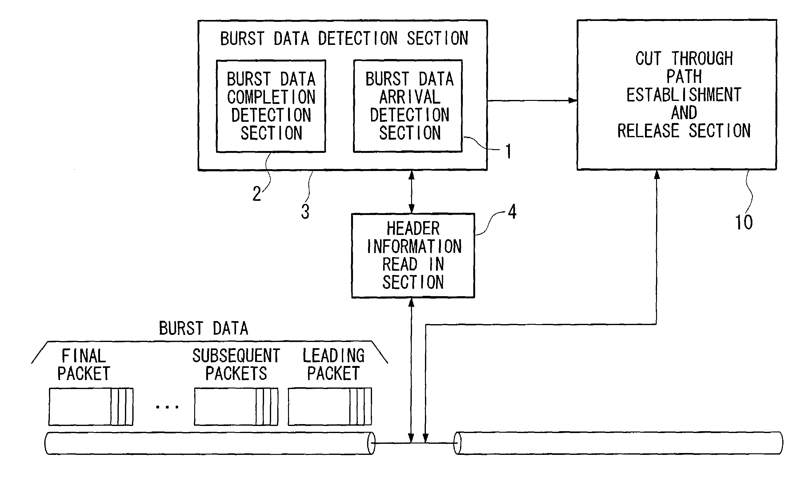
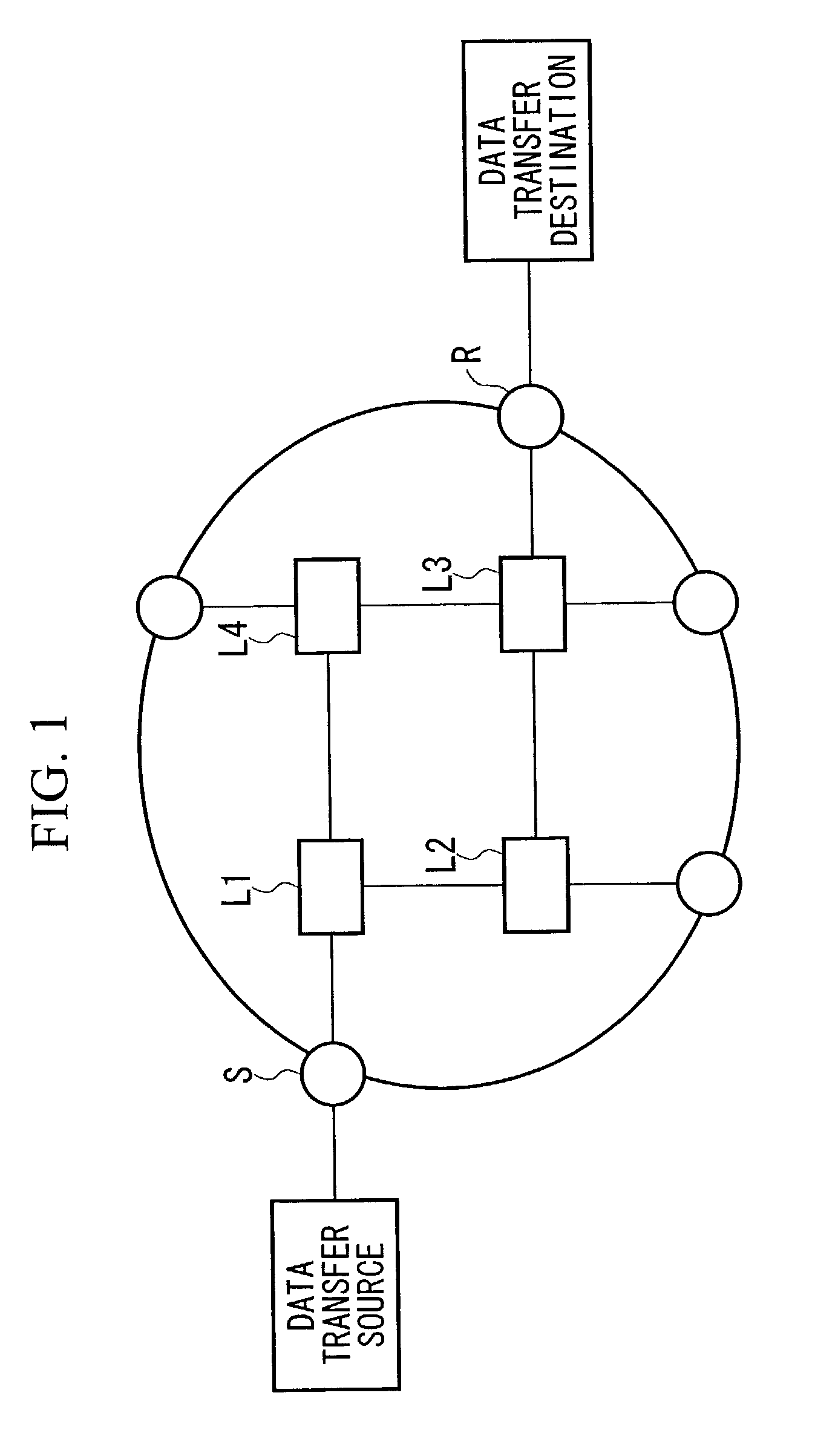
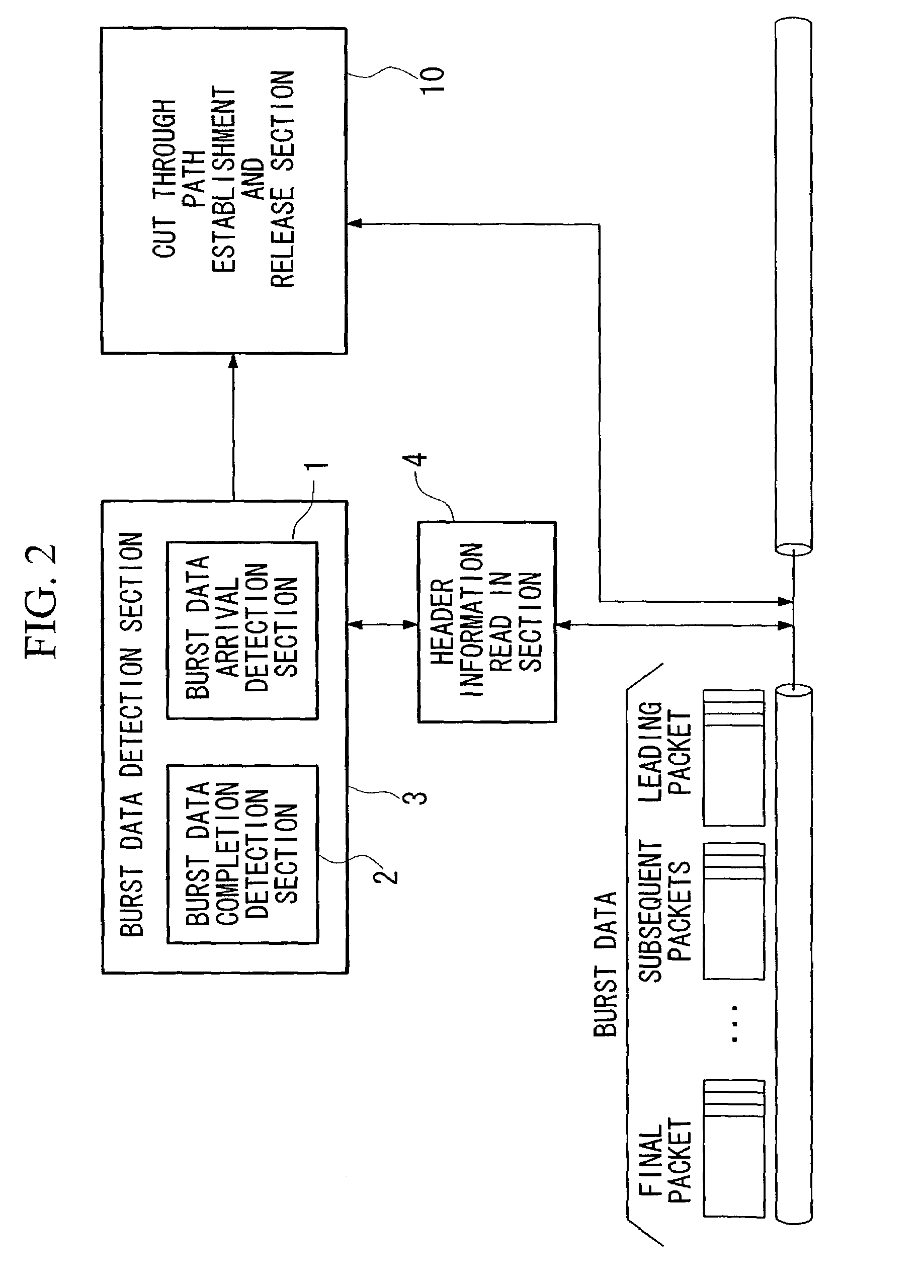
[0192]An optical communication network according to the first embodiment of the present invention will now be explained with reference to FIGS. 1 through 7. FIG. 1 is a schematic diagram showing an optical communication network according to an embodiment of the present invention; FIG. 2 is a diagram for explanation of a burst data detection section and a cut through path establishment and release section of the first embodiment of the present invention; FIG. 3 is a diagram showing the structure of a packet which is used in the embodiments of the present invention; FIG. 4 is a block diagram for a burst data arrival detection section of the first embodiment of the present invention; FIGS. 5 and 6 are flow charts showing the operation for dynamically setting a limit value, with the first embodiment of the present invention; and FIG. 7 is a diagram for explaining a data base of the first embodiment of the present invention.

[0193]As shown in FIG. 1, the present invention is an optical co...

embodiment 2

[0208]The second embodiment of the present invention will now be explained with reference to FIGS. 8 and 9. FIG. 8 is a block diagram for a burst data detection section and a cut through path establishment and release section of the second embodiment of the present invention. And FIG. 9 is a flow chart showing the operation of the cut through path establishment and release section of this second embodiment of the present invention.

[0209]In this second embodiment, as shown in FIG. 8, the cut through path establishment and release section 10 comprises an L1 retaining section 11 which retains burst lengths L1 which represent burst data amount information relating to the burst data which is being transferred by the cut through paths which are already established; and, as shown in FIG. 9, when there are no wavelength resources for newly establishing a cut through path to transfer newly arrived burst data, the burst lengths L1 of the burst data which is being transferred by the already es...

embodiment 3

[0214]The third embodiment of the present invention will now be explained with reference to FIGS. 10 and 11. FIG. 10 is a block diagram for a burst data detection section and a cut through path establishment and release section of the third embodiment of the present invention. And FIG. 11 is a flow chart showing the operation of the cut through path establishment and release section of this third embodiment of the present invention.

[0215]In this third embodiment, the cut through path establishment and release section 10 comprises an Lreg detection section 12 which, when there are no wavelength resources for newly establishing a cut through path to transfer newly arrived burst data, detects not yet transferred burst lengths Lreg which represent the not yet transferred burst data amounts of the burst data which is being transferred by the cut through paths which are already established, and, if according to the results of detection by the Lreg detection section 12 the not yet transfer...


PUM


Abstract

The present invention relates to a node which is used in the structure of an optical communication network. This node has a signal transmission function for performing data transfer and a signal receiving function for performing data signal reception, and includes a unit for establishing and releasing a cut through path to a next stage node. Moreover, it includes a unit for detecting the arrival of a leading packet of burst data, and the unit for establishing and releasing the cut through path includes a unit for establishing a cut through path to the next stage node, when the arrival of a leading packet of burst data is detected by the leading packet arrival detection unit.

Description

BACKGROUND OF THE INVENTION[0001]1. Field of the Invention[0002]The present invention relates to a node (an optical dynamic burst switch) which takes advantage of optical communication, and which is included in an optical communication network which uses optical wavelengths as a communication medium for burst data transfer.[0003]This application is based on patent applications Nos. 2001-337587, 2001-337590, 2001-337601, 2001-337891, 2001-338050, 2002-060102, 2002-060119, and 2002-060127 filed in Japan, the contents of which are incorporated herein by reference.[0004]2. Description of the Related Art[0005]In data transfer by an IP (Internet Protocol) network, a router which acts as a node reads in the header information of an IP packet, and transfers that IP packet along a path to its destination. This is performed repeatedly between a plurality of nodes, and as a result the IP packet makes its way to the desired destination. With this type of transfer method for an IP packet it beco...

Claims


Application Information

Patent Timeline
IPC IPC(8): H04J14/00H04Q11/00
CPCH04Q11/0005H04Q11/0066H04Q2011/005H04Q2011/0064H04Q2011/0073
Inventor SHIOMOTO, KOHEIYAMANAKA, NAOAKIOKI, EIJI
Owner NIPPON TELEGRAPH & TELEPHONE CORP
Why Eureka
Try Eureka