Interlocking mat system for construction of load supporting surfaces

a technology of interlocking mats and supporting surfaces, which is applied in the direction of single unit paving, transportation and packaging, roads, etc., can solve the problems of affecting the construction efficiency of the roadway, the labor intensive use of wooden boards, and the inability to remove individual boards. , to achieve the effect of reducing the labor intensity and time-consuming and labor-intensive process, and reducing the cost of labor

Inactive Publication Date: 2004-02-24
COMPOSITE MAT SOLUTIONS L L C
View PDF13 Cites 101 Cited by
  • Summary
  • Abstract
  • Description
  • Claims
  • Application Information

AI Technical Summary

Benefits of technology

The mat system of the present invention is a durable, reusable mat system which can be utilized to construct roadways and other support surfaces. Moreover, the mat system of the present invention can be horizontally expanded in all lateral and longitudinal directions to provide the desired coverage by the roadway or other support surface being constructed. Due to the generally uniform outward configuration of the individual mats of the present invention, a roadway and / or other support surface can be installed in a single layer by simple placement of the individual mats. Additionally, this generally uniform outward configuration allows for great flexibility in the installation process. These qualities greatly reduce the time, expense and labor requirements associated with installing and removing the disclosed invention.
It is a further object of the present invention to provide a mat system comprising a plurality of wholly interchangeable individual mats which can be installed in a single layer by simple relative placement.

Problems solved by technology

While individual wooden boards or planks have been used to construct support surfaces for some time, this method of building roadways and other load bearing surfaces suffers from some very significant disadvantages.
Because such a large number of individual wooden boards are generally required to construct a typical roadway or equipment support surface, the use of wooden boards can be very labor intensive, since each board must first be individually positioned, and thereafter nailed or otherwise secured in place.
Removal of said individual boards can also be a very time consuming and labor intensive process, since each board must be separated or pulled apart prior to being removed from the location.
While such conventional mat systems may represent an improvement over the use of individual boards for the construction of roadways and other equipment support surfaces, the aforementioned conventional mat systems suffer from a number of serious shortcomings.
Although such conventional mats may reduce labor requirements compared to individual wooden boards, significant amounts of time, effort and manpower are still required to install said mats at a remote location since most, if not all, of said conventional mat systems require the use of multiple layers.
This multiple layer requirement leads to significant redundancy of effort in connection with both the installation and removal of said mats.
Additionally, the design of conventional mat systems can lead to degradation of the ground underlying said mats, as well as the structural integrity of the mats themselves.
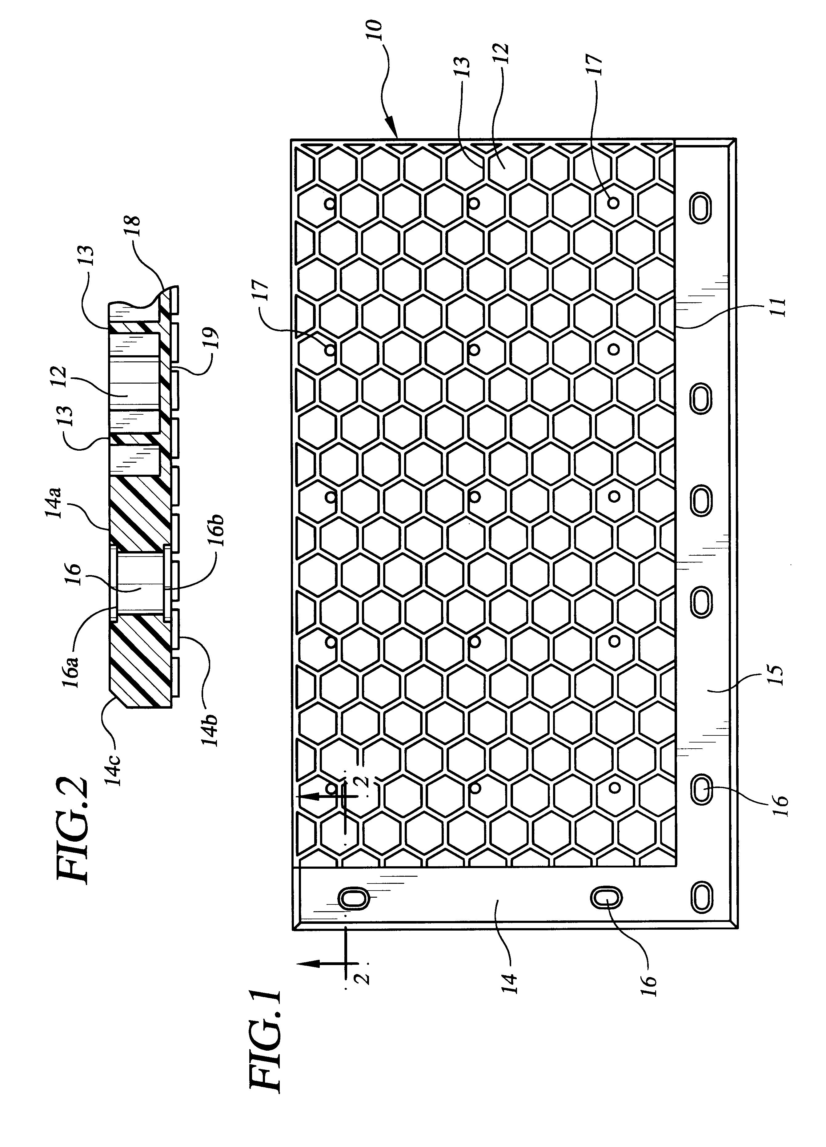
Trucks and other heavy equipment passing over the mats place a downward load on said mats, which in turn causes mud to be pumped up through the numerous gaps or seams of the mats.
This pumping action creates voids beneath the mats which, over time, can lead to severe deformities in the roadway surface.
Because the mats bridge over these underlying voids, the mats thereafter have a tendency to break or splinter when subjected to loading from above, especially after such wooden mats dry out.
Conventional wooden mats also suffer from significant rotting problems, since the mats can become inundated with rain water and various other contaminants from above, as well as mud from below.
This mixture of water, mud and other contaminants will often invade into the seams or gaps between the boards of said mats, causing the wooden mats to rot from within.
Although conventional mat systems are designed to be reusable, the mats are still subject to significant repair and replacement expense.
The design of these conventional mats can also lead to significant environmental problems, because mud and other contaminants can saturate the mats and collect within the numerous seams or gaps of said mats.
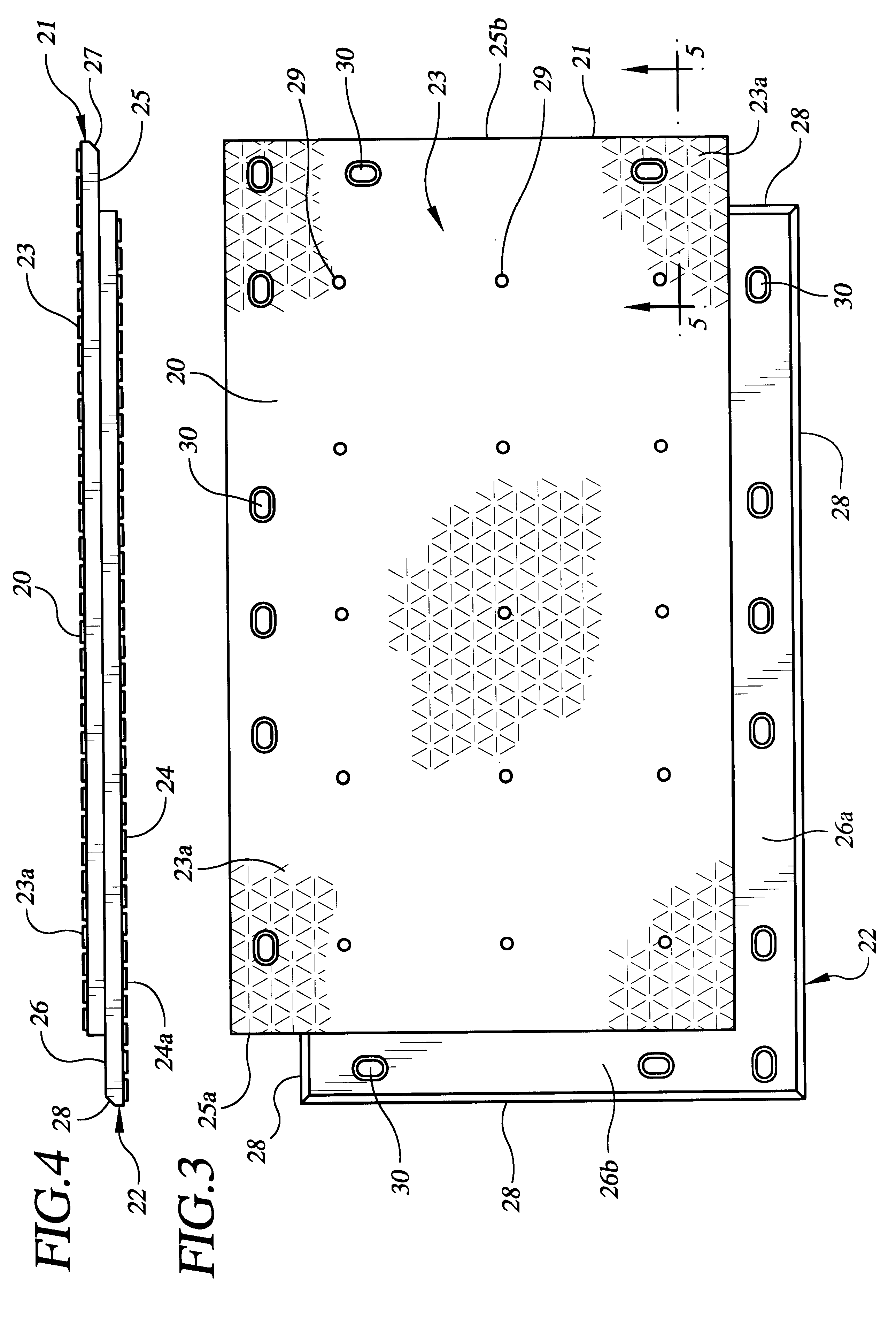
Yet another shortcoming with existing mat systems is the failure of individual mats to lock or interconnect with one another on all sides.
However, said patents describe offset extensions comprised of individual planks which are subject to warpage, cracking or splintering when exposed to environmental elements, as well as loading from trucks or other heavy equipment using the work surface.
The referenced patents to Waller also describe the additional step of securing a plank or board between the individual mats, which significantly increases labor requirements associated with these mat systems.
This factor makes the installation process significantly more complicated than that of the present invention, and greatly increases labor costs associated with said installation.
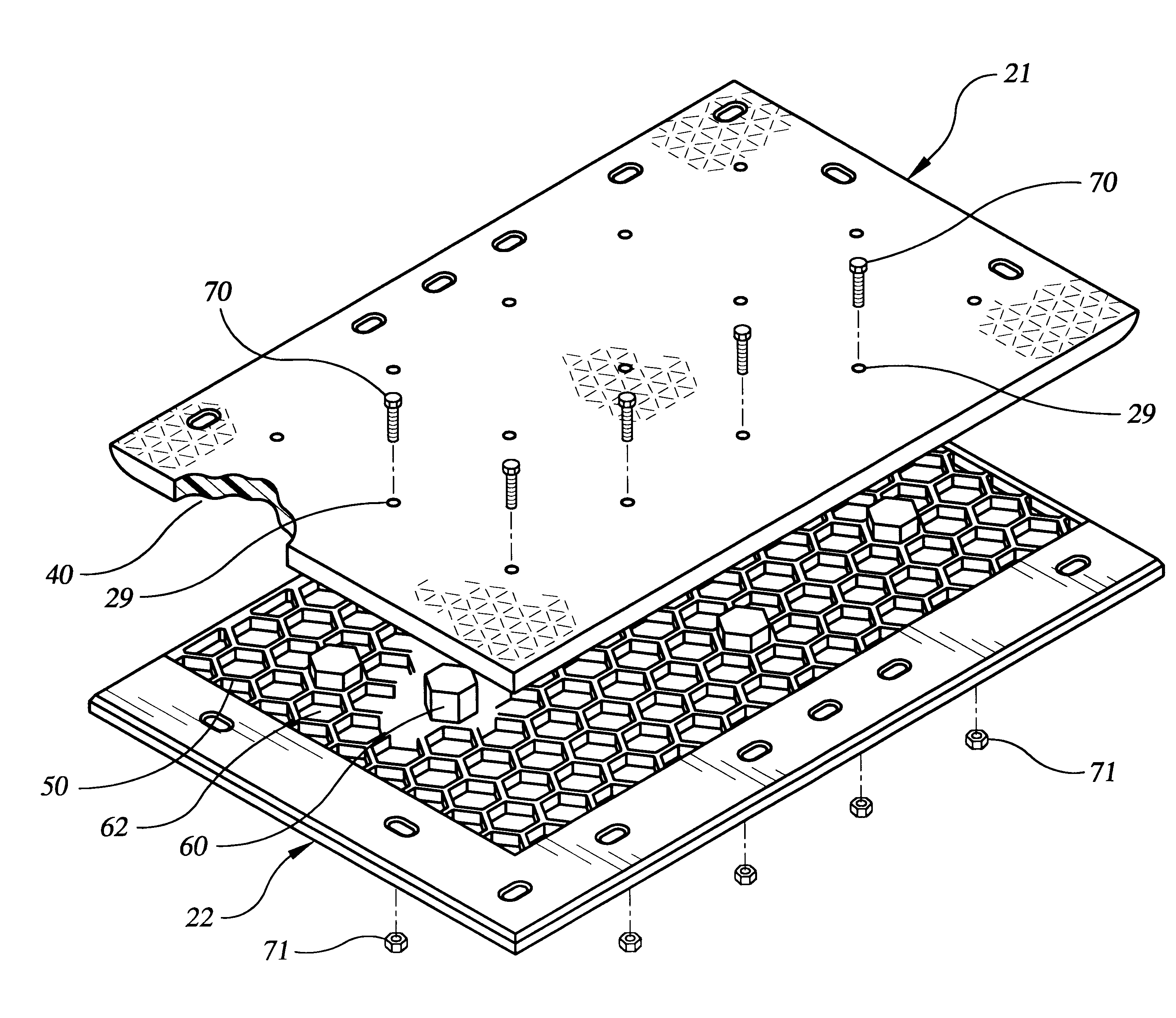
However, the mats disclosed in the '551 patent do not include traction promoting elements in the form of raised strips extending outward from the planar surfaces of the individual mats.
More significantly, the '551 patent does not disclose the placement of such raised strips proximate to, and in general alignment with, the internal cell forming walls of the individual mats.
In addition, the mats disclosed in the '551 patent contain offset peripheral edges, but lack means for mechanically affixing said mats to adjacent mats.
Further, the mats described in the '612 patent also lack traction promoting elements on the outer planar surfaces of said mats, as well as means for mechanically joining said mats to other adjoining mats.
However, when a large number of such raised members are not positioned in such a manner, the relatively thin outer skin defining the roughly planar surfaces of the mats can become easily deformed by such direct loading.
This temperature variance can result in a differential in shrinkage rates between said half-pieces which can, in turn, generate forces which cause said half-pieces to curl and / or pull apart from one another.
As trucks or other vehicles travel across roadways or other support surfaces constructed from the mat system disclosed herein, mats of conventional mat systems can have a tendency to pull or "walk apart" from one another.

Method used


Image

  • Interlocking mat system for construction of load supporting surfaces
  • Interlocking mat system for construction of load supporting surfaces
  • Interlocking mat system for construction of load supporting surfaces

Examples


Embodiment Construction

In the preferred embodiment, the individual mats of the present invention are comprised of two mirror-image half-piece components which are affixed together to form a single mat. FIG. 1 depicts a half-piece component 10 of the present invention. In the preferred embodiment, an area of reduced material is in the form of open faced cellular structure, specifically a plurality of hexagonal honeycombs 12. Such open faced cellular structure is generally comprised of interconnected cell forming walls 13, which define said hexagonal honeycombs. In the preferred embodiment, said cell forming walls are integrally attached to a roughly continuous skin along one edge of said honeycombs, which in turn defines a generally planar work surface on one side of said half-piece. Two adjacent peripheral edges 14 and 15 of said half-piece 10 define areas having roughly continuous outer surfaces. Additionally, one or more recessed receptacles 16 are disposed through edges 14 and 15. A plurality of holes ...


PUM

PropertyMeasurementUnit
mechanicalaaaaaaaaaa
densityaaaaaaaaaa
durableaaaaaaaaaa

Abstract

A reusable mat system for the construction of load bearing surfaces, such as temporary roadways and equipment support surfaces, over unstable or unsubstantial terrain, comprising durable, interlocking individual mats which can be quickly and easily installed in a single application, and which can thereafter be easily removed and stored until needed again. The individual mats of the present invention interlock on all sides to form stable and continuous load bearing surfaces, and exhibit favorable traction characteristics.

Description

STATEMENTS AS TO RIGHTS TO INVENTIONS MADE UNDER FEDERALLY-SPONSORED RESEARCH AND DEVELOPMENT(Not Applicable)1. Field of the InventionThe present invention relates to a reusable mat system for the construction of load bearing surfaces, such as temporary roadways and equipment support surfaces, over unstable or unsubstantial terrain. More particularly, the present invention relates to a reusable system of durable, interlocking individual mats which can be quickly and easily installed in a single application to construct temporary roadways and equipment support surfaces, and which can thereafter be easily removed and stored until needed again. More particularly still, the present invention relates to a reusable mat system comprising generally identical mats constructed of thermoplastic resins or other moldable materials, which interlock on all sides to form stable and continuous load bearing surfaces, and which exhibit favorable traction characteristics.2. Description of the Related A...

Claims


Application Information

Patent Timeline
Patent Type & Authority Patents(United States)
IPC IPC(8): E01C9/00E01C9/08
CPCE01C9/086Y10T428/24157Y10T428/24149
Inventor SEAUX, ORES PAULSEAUX, KENNETH P.ROGERS, DONALD S.
Owner COMPOSITE MAT SOLUTIONS L L C
Why Eureka
Try Eureka