Facet fixation and fusion wedge and method of use

a wedge and facet technology, applied in the field of spinal stabilization and fusion, can solve the problems of lateral offset, hyperlordosis, and/or intervertebral foraminal stenosis at the level of instrumentation, and the risk of patient further injury,

Active Publication Date: 2008-10-16
DEPUY SPINE INC (US)
View PDF99 Cites 189 Cited by
  • Summary
  • Abstract
  • Description
  • Claims
  • Application Information

AI Technical Summary

Benefits of technology

[0009]Next, at least one drive screw can be disposed within the cavity of the wedge body such that a threaded portion of the screw(s) protrudes from each opening of the opposed bone-contacting surfaces. The screw can be positioned such that a longitudinal axis of the screw is substantially collinear with a longitudinal axis of the wedge body. Furthermore, two screws can be disposed within the wedge body such that each screw is mounted on opposite sides of a longitudinal axis of the wedge body. Next, a screw head can extend from a proximal end of the screw such that the screw head is positioned adjacent the trailing edge of the wedge body so as to be surgically accessible. The screw head can allow for a user to exert a rotational force on the screw.
[0013]The opposed bone contacting surfaces of the wedge body can include various features which facilitate and / or enhance spinal stabilization and / or fusion. For example, at least one of the opposed bone-facing surfaces can be textured to help prevent sliding of the wedge relative to the opposed faces of the facet joint. Next, at least one of the bone-contacting surfaces can include protrusions (e.g., barbs) capable of enhancing placement of the implant within the facet joint by increasing a friction between the bone-facing surface and the corresponding facet face. Additionally, the bone-contacting surface can be porous thereby allowing for bone in-growth into and / or through the wedge body thereby allowing the wedge body to be further solidified within the facet joint.
[0015]In another aspect, the method can include surgically delivering at least one intra-facet wedge to a facet joint in an intra-facet configuration. Similar to above, a screw can be disposed within the wedge body such that a threaded portion of the screw protrudes from the opposed bone-contacting surfaces of the wedge body. Next, the method can include engaging the threads to opposing faces of the facet joint, and rotating the thread to advance the wedge body into the facet joint. The method can further include adding a fusion-promoting bioactive material to the wedge body thereby allowing for a single spinal implant capable of spinal fixation and fusion. As an added advantage, the method can allow for the spinal implant to be delivered in a minimally invasive procedure.

Problems solved by technology

Such a technique has associated with it the risk of further injury to the patient as such translamina facet instrumentation can be difficult to place in such a way that it does not violate the spinal canal and / or contact the dura of the spinal cord or the nerve root ganglia.
Further, trans-facet instrumentation has been known to create a rotational distortion, lateral offset, hyper-lordosis, and / or intervertebral foraminal stenosis at the level of instrumentation.
TLFS and TFPS implants provide reasonable mechanical stability, but, as noted above, they can be difficult to place, have long trajectories, and surgical access can be confounded by local anatomy.
In some instances these implants can result in some degree of foraminal stenosis.

Method used


Image

  • Facet fixation and fusion wedge and method of use
  • Facet fixation and fusion wedge and method of use
  • Facet fixation and fusion wedge and method of use

Examples


Embodiment Construction

[0035]Certain exemplary embodiments will now be described to provide an overall understanding of the principles of the structure, function, manufacture, and use of the devices and methods disclosed herein. One or more examples of these embodiments are illustrated in the accompanying drawings. Those skilled in the art will understand that the devices and methods specifically described herein and illustrated in the accompanying drawings are non-limiting exemplary embodiments and that the scope of the present invention is defined solely by the claims. The features illustrated or described in connection with one exemplary embodiment may be combined with the features of other embodiments. Such modifications and variations are intended to be included within the scope of the present invention.

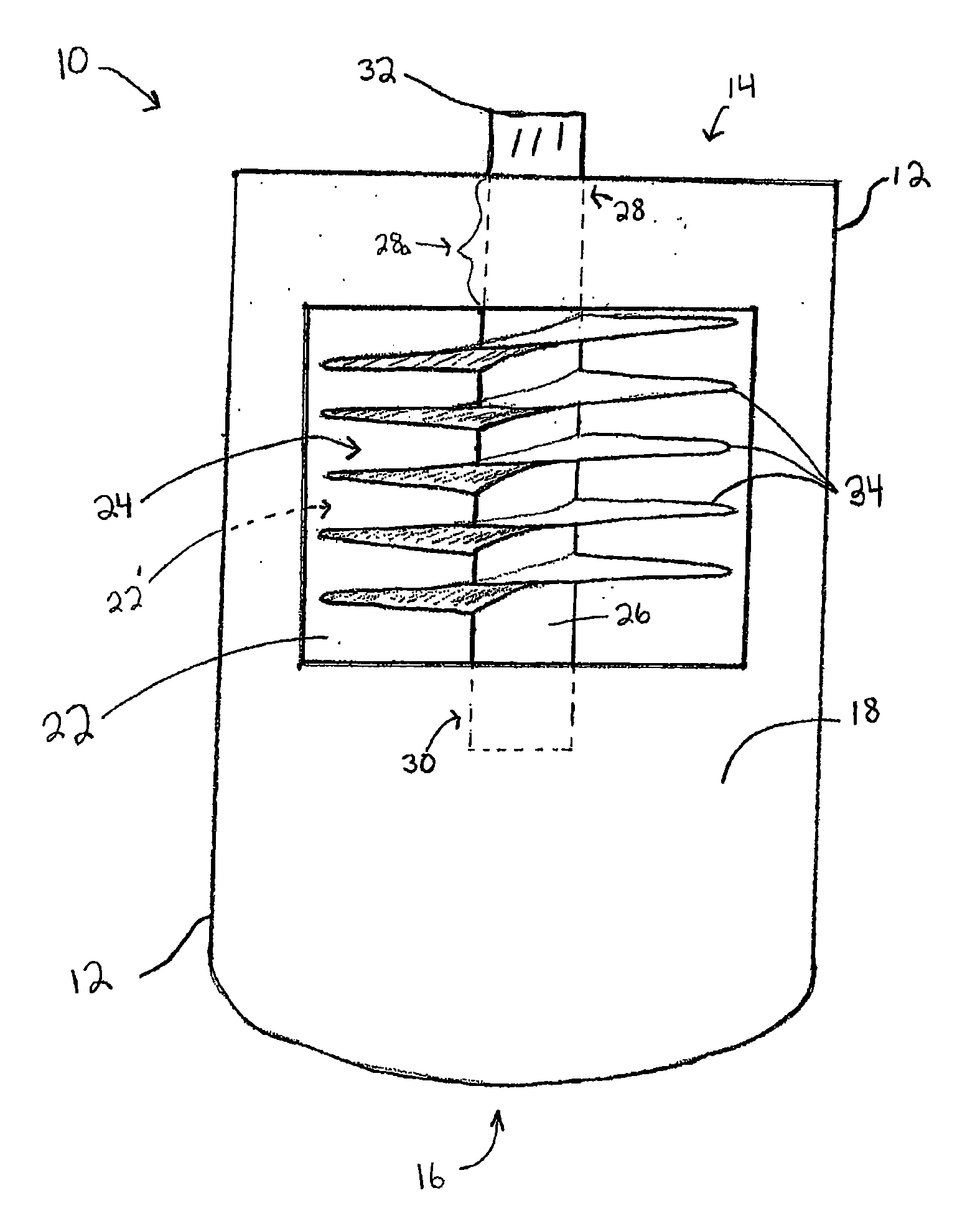
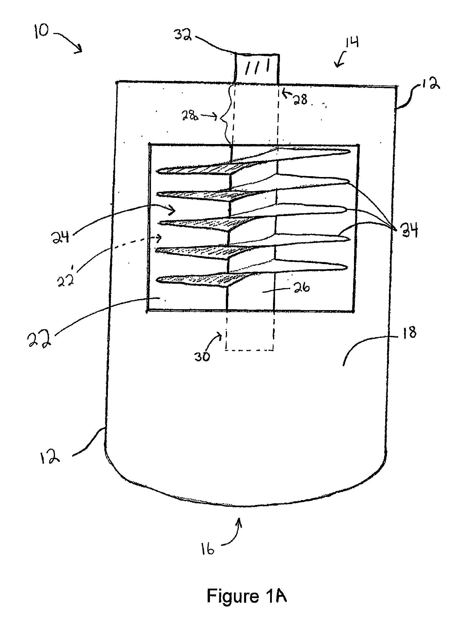
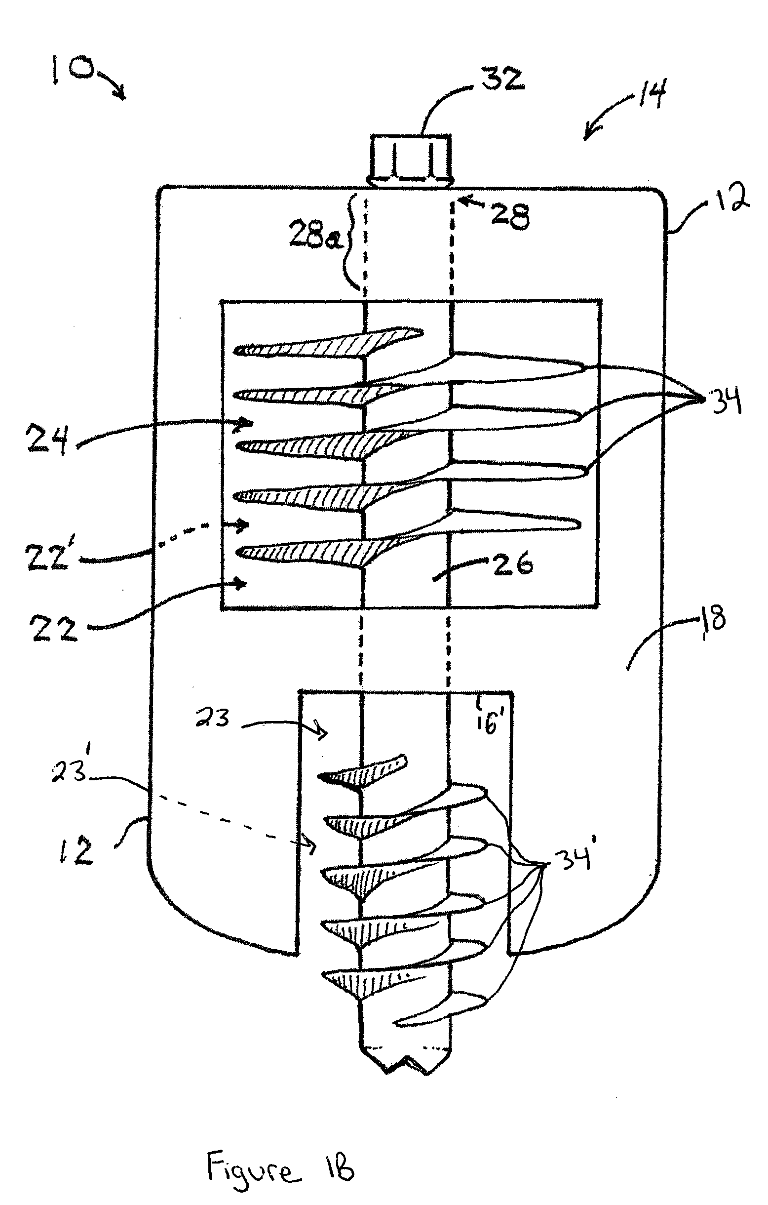
[0036]In general, the spinal implants disclosed herein are configured for intra-facet placement within a facet joint. That is, the implants are configured to be placed in the plane of the facet joint,...


PUM


Abstract

A spinal implant including an at least one screw disposed within a wedge body is herein provided. The implant can be configured for placement with a facet joint in an intra-facet delivery. Furthermore, the implant can include a fusion-promoting bioactive material thereby providing a single device capable of spinal stabilization and / or fusion. Furthermore, a method of placing such an implant within a facet joint in an intra-facet orientation is hereby provided.

Description

FIELD OF THE INVENTION[0001]The present invention relates to methods and devices for spinal stabilization and fusion, and particularly to stabilization and fusion of a facet joint.BACKGROUND OF THE INVENTION[0002]The vertebrae in a patient's spinal column are linked to one another by the intevertebral disc and the facet joints. This three joint complex controls the movement of the vertebrae relative to one another. Each vertebra has a pair of articulating surfaces located on the left side, and a pair of articulating surfaces located on the right side, and each pair includes a superior articular surface and an inferior articular surface. Together the superior and inferior articular surfaces of adjacent vertebra form a facet joint. Facet joints are synovial joints, which means that each joint is surrounded by a capsule of connective tissue and produces a fluid to nourish and lubricate the joint. The joint surfaces are coated with cartilage allowing the joints to move or articulate rel...

Claims


Application Information

Patent Timeline
Patent Type & Authority Applications(United States)
IPC IPC(8): A61B17/70A61B17/58A61F5/00A61F2/44
CPCA61B17/7064
Inventor FISHER, MICHAEL ALANTECHIERA, RICHARD C.MICKIEWICZ, CHRISTOPHERO'NEIL, MICHAEL
Owner DEPUY SPINE INC (US)
Why Eureka
Try Eureka