Computer input device enabling three degrees of freedom and related input and feedback methods

a computer input and freedom technology, applied in the direction of instruments, electric digital data processing, cathode-ray tube indicators, etc., can solve the problems of difficult learning for the average user, the mouse cannot provide simultaneous control of more than two degrees of freedom, and the computer system requires more, so as to improve the view, extend the functionality of the application, and facilitate placement

Inactive Publication Date: 2007-06-28
POSTON TIMOTHY +1
View PDF1 Cites 208 Cited by
  • Summary
  • Abstract
  • Description
  • Claims
  • Application Information

AI Technical Summary

Benefits of technology

[0062] By the configuration of its drivers, on receiving signals from an application designed to use a standard mouse the present invention reports only the changes (Δx, Δy) expected, together with the changes in button state. However, an application that requests Δθ sees that information also, by using a specified protocol. For an application originally designed to use only a standard mouse, but which supports the creation of third-party ‘plug-ins’, such a plug-in may extend the application's functionality to include one or more of the interaction mechanisms here described: supplied to the user as an optional part of the present invention, such a plug-in avoids the need to wait for a version of the application where support for such mechanisms is programmed by the application's creator. Alternatively, the invention may emulate a joystick by responding to standard joystick protocols, enabling the mouse-equipped user to interact with applications previously created for joystick input.
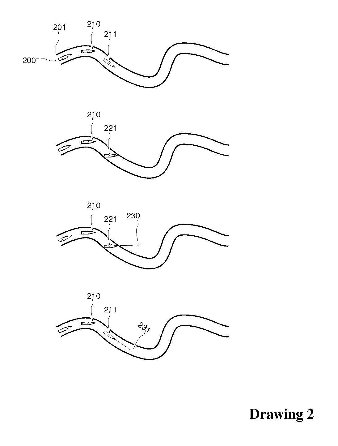
[0063] When an application requires the user to modify only the (x, y) position of a cursor, as in selecting a button or link by moving the cursor there and clicking, the application may either collect and ignore Δθ, or simply not collect it. In this situation, the user notices no difference from a standard mouse, since (for example) a cursor then moves without rotating. However, an application may couple Δθ to the behaviour of various objects on screen. Revisiting the situation of Drawing 2, for example, Drawing 10 shows the approach of a cursor 1010 in (x,y) mode, unrotating, as though moved by a standard mouse. When the cursor 1010 touches 1015 the boat, the boat is highlighted 1020, and the cursor may adopt a form signalling turnability, such as 1011. Holding down a button invokes the drag mode appropriate to this object, which includes rotation, perhaps with a ‘gear ratio’. In our preferred implementation, here and elsewhere where a cursor drags a rotatable object, the cursor rotates visibly itself, maintaining a rigid positional relationship. A single drag movement now suffices to move the boat along the river 1001 through the sequence of positions 1030, without awkward motion of the wrist and elbow. Similarly, this mouse enables a ‘fire-as-you-turn’ game mode (Drawing 11), a faster version of interactive crosswords and the game Raku (Drawing 12), and the easy placement of labels (Drawing 13) and drawing elements (Drawing 14). Drawing 15 shows a unified widget controlling a curve point and direction simultaneously, and drawings 16 and 17 show the extension of this to key frames, controlling motion along a curve.
[0064] A 3-degree-of-freedom device such as the present invention can never simultaneously control the six degrees of freedom in rigid 3D motion. However, it can control position and orientation separately, with a natural mapping to each. Drawing 18 shows control of position (x, y, z), while Drawing 19 shows control of orientation. The mechanism above would evidently be useful in any software that displays 3D objects, from gearbox designs to seismic data to MRI scans: all these objects must frequently be moved, for an improved view. It is also useful in controlling the operation of a scanning system, where the ‘object’ to be moved represents not an object such as a gearbox or a brain scan, but the solid region in which the system is to be instructed to acquire data. The present invention makes this easier while remaining interoperable with the standard mouse for its familiar functions. It is also frequently important in 3D display to control the position of a cut-away ‘clipping plane’: Drawing 20 shows convenient manipulation of this in the present invention. A similar control applies to the specification of a single plane in which a scanning system is to be instructed to acquire data. Cursor manipulation defining 3D paths is shown in Drawing 21, with a 3D analogue of the 2D animation key frame logic in Drawings 16 and 17. Drawing 22 shows improved selection of colour using the present invention, by a means equally applicable to the reflection properties of a surface, or to any three-parameter selection that a user must make. Drawing 40 illustrates a selection box that using the present invention could be added to a 3D graph with one point selection, one translational drag, and one rotation, as opposed to many more for any schema using a standard mouse: more actions are discussed in the Detailed Description. Drawing 41 illustrates that selections within a draggable widget such as a palette or tool-tip can be made while dragging it. Drawing 42 illustrates that the user can turn a brush tip while moving it (changing the effect of the brush) or change the state of a more general object while moving it: in the example shown the user makes it move its jaw (“chew gum”) and navigate the screen (“walk”) at the same time.
[0065] The present invention also includes the replacement of keyboard or submenu options that modify the effect of a click, by gestural features using rotation rather than holding down the Shift, Ctrl, or Alt key while performing a mouse click, to modify its effect, or moving through submenus.

Problems solved by technology

All these can be controlled with a standard computer mouse, but not simultaneously: The conventional mouse does not provide simultaneous control of more than two degrees of freedom.
However, many tasks of manipulating 2D or 3D objects in computer systems require more than this.
Other available devices, such as a joystick, control three or more degrees of freedom but differ sufficiently from the standard mouse that the required learning is hard for the average user, who also has to retrain to achieve previously mastered tasks like cursor control.
These groups are hard to coordinate for simultaneous control.
This extends the familiar mouse for three-dimensional manipulation, while allowing standard 2D Graphical User Interface tasks, but at the added cost of a camera with deep focus and of considerable image processing power, and is hard to implement unless (claim 4) “the working surface comprises a patterned surface”, with desk space and cleaning requirements avoided by the conventional mouse.
Such difficulties have prevented its commercialization.
The delicacy and cost of its moving parts limits its use to applications where such force display is essential.
The added ring therein disclosed, as with a scroll wheel, requires control by different muscle groups of the user, which are not easy to coordinate.
Therefore, the 3D object is smoothly moved from a starting position and orientation to a target position and orientation, but the device cannot serve as a plug-in substitute for a standard 2D mouse.
The disclosure discusses the use of the device for 3D rotation, but the method disclosed does not allow the user to perform arbitrary rotations, with the 3-parameter variability of normal physical rotation.
Any 3D rotation can in fact be produced by a sequence of such standard-axis rotations, but for a user to achieve a desired orientation the sequence of alternating axis selections and rotations is likely to be long.
The display details aside, the problem here is again that the user must use multiple drag movements where a single one would be convenient.
Other schemes exist, but by using a standard mouse they are subject to similar difficulty.
Much mouse-driven software provides an option of ‘drawing’ directly with a mouse, creating a curve that follows the cursor as though it were a pencil tip: however, a mouse is hard to use with the necessary delicacy, and many users prefer a digital drawing pad where the reported (x, y) position is that of the tip of a pencil-like stylus.
Using a mouse to control the position of an object in a three-dimensional display is thus a tedious and laborious process, with many disadvantageous methods widely in use.
This results in a great deal of transfer between windows, each time requiring a cursor motion and then at least one new drag movement, before the user can achieve an appropriate configuration as judged by some desired effect in the object, scene or view under construction.
Moreover, the scarce resource of ‘real estate’ on the monitor is used lavishly by this multiplicity of windows, making each of the individual views small, thus concealing detail, and limiting the space available to other features of the interface.
Some software uses multiple monitors to mitigate this problem, at substantial cost in equipment, in space occupied and in the separate displays that the user must watch.
This provides some support for these rotations, but the need for intermediate large turns, for a user whose goal is a ‘tweaking’ twist about the axis 742, adds to the difficulty of manipulation.
The user's hand must abandon the keyboard more completely than even with one mouse, so that typing in a label or using a simultaneous key becomes more cumbersome; the frequent use in interfaces of pressing a mouse button with Shift or ALT pressed, for an effect different from a simple press, would now require that one hand returns to the keyboard, and locates the relevant key.
Moreover, a pair of standard mice is a mismatch to the object motion problem, since the combined four degrees of freedom are more than needed for translation or rotation alone (so that some aspect of the change in the position data (x1, y1, x2, y2) must be arbitrarily ignored, and the user must learn which), and not enough to control both together.
This is not a satisfactory situation.
However, the analogous family tree 807 contains multiple paths between distinct nodes, although as a ‘directed’ graph a family's relationships cannot contain loops without self-ancestry.
Even where a graph has a crossing-free embedding, it may not have one that satisfies relevant constraints such as directionality, birth order, space for labels, etc., so that crossings easily become unavoidable.
With multiple crossings, a planar graph is often visually useless.
This has obvious advantages for display, except that (in the current standard interfaces) 3D objects are difficult and tedious for a user to interact with.
With a standard mouse it is hard even to turn a 3D embedded graph for the most convenient view: in any current view, some nodes and edges are closer, and may mask others.
Moreover, when the user's region of interest changes, there is often a need to turn the displayed view.
It is thus useful in multiple ways to rotate the displayed object, but with a standard mouse it is inherently difficult to control general rotations.

Method used


Image

  • Computer input device enabling three degrees of freedom and related input and feedback methods
  • Computer input device enabling three degrees of freedom and related input and feedback methods
  • Computer input device enabling three degrees of freedom and related input and feedback methods

Examples


Embodiment Construction

[0116] While this specification concludes with claims particularly pointing out and distinctly claiming that which is regarded as the invention, it is anticipated that the invention can be more readily understood through reading the following detailed description of the invention and study of the included drawings.

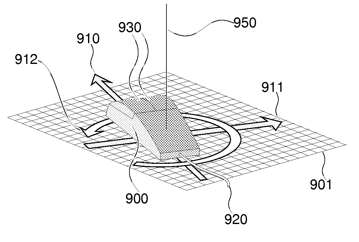
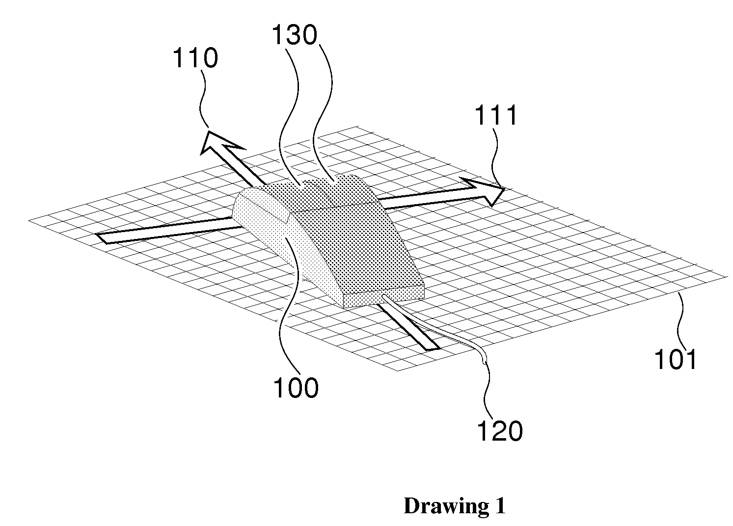
[0117] The present invention provides a method and device for reporting changes in location and orientation of an object moving against a planar surface, with a response identical to that of a location-only mouse in any application which addresses such a mouse by the standard protocols, but on demand making data available on angular change about the normal to the planar surface. We refer to such a device as a translation-rotation mouse.

[0118] The preferred embodiment of the invention is to provide information regarding a planar rotation simultaneously with translation motion of an object as shown in Drawing 9. Drawing 9 shows a representative physical embodiment 900 of t...


PUM


Abstract

Disclosed herein are a system and method for simultaneously reporting changes in location and orientation of an object moving over a planar surface and forming part of a computer input device, interoperably with a conventional mouse where reporting only location is in question. Further the present invention provides improved ways of user interaction with computer displays of two and three dimensional data and structures.

Description

FIELD OF THE INVENTION [0001] This invention, in general, relates to devices enabling human-computer interfaces. More particularly, this invention relates to a computer input device enabling three degrees of freedom and related methods for input to the computer and feedback from it. BACKGROUND OF THE INVENTION [0002] Humans have given instructions to computers in many ways. Rearranging the gears in Boole's 19th Century ‘analytical engine’, rearranging the wires in early electronic machines, programming by making or changing holes in cards or paper and typing letters and numbers that are echoed on a monitor are some such ways. From the year 1968 the method of inputting instructions to a computer by moving and clicking a mouse (U.S. Pat. No. 3,541,541 issued Nov. 17, 1970, X-Y Position Indicator For A Display System) has been devised. This method first appeared commercially in 1981 in the Xerox Star workstation, more than a decade after the patent was issued. Other devices have since ...

Claims


Application Information

Patent Timeline
Patent Type & Authority Applications(United States)
IPC IPC(8): G09G5/08G06F3/033G06F3/0354G06F3/038
CPCG06F3/0317G06F3/03544G06F3/038G06F3/0383
Inventor POSTON, TIMOTHYSRIKANTH, MANOHAR BALAGATTE
Owner POSTON TIMOTHY
Why Eureka
Try Eureka