Method and apparatus for interconnecting paneling

a technology of interconnection and paneling, which is applied in the direction of walls, constructions, flooring, etc., can solve the problems of unplanned expansion or shrinkage of the floor covering and/or sub, undesired gaps, and complex installation time-consuming, so as to reduce the amount of time and labor required, the effect of simple design

Inactive Publication Date: 2004-02-26
EVJEN JOHN M
View PDF52 Cites 108 Cited by
  • Summary
  • Abstract
  • Description
  • Claims
  • Application Information

AI Technical Summary

Benefits of technology

0024] The present invention further provides an extremely flexible paneling system that can be configured to meet the requirements of complex floor plans or wall configurations, including those floor plans that involve intersecting passageways and several associated rooms.
0025] A panel according to the subject invention may have a top side covered by a wood veneer or other attractive wear surface, and an underside which may be covered by a rubber cushion layer. The present invention confers simplicity of design, ease of assembly, and a significant decrease in the amount of time and labor required for installation. These same advantages are conferred in disassembly and reassembly, if desired. The advantages of the subject invention apply to panels of any thickness as well as to panels that serve a variety of purposes. For example, the present invention is applicable to indoor and outdoor floors and walls, where the panels have a variety of shapes and thickness.

Problems solved by technology

Disadvantages of this installation method are that installation is complex and time consuming and disassembly requires the panels be broken from the underlying floor.
Further, this floor covering does not take into account the inevitable expansion or shrinkage of the floor covering and / or sub-flooring due to changes in humidity and / or temperature.
Thus, the floor panels can drift apart and result in the formation of undesired gaps, for example, in those joints where the glue connection is broken.
Where all of the side edges of a panel are tongue and groove joint elements, installation of such floor panels requires considerable physical manipulation to connect the floor panels without disengaging the joints of adjacent panels.
Thus, floor panels that are interconnected using solely tongue and groove joints on all side edges are difficult to assemble and disassemble.
The floor covering obtained in this manner is difficult to disassemble.
In addition, assembling the flooring system was particularly messy when the excess glue leaked from between the joints.
While these panels disclose various interconnecting means, they do not provide optimum, durable panel coupling while ensuring ease of assembly or disassembly.
Thus, these and other known panels used to form floors, walls, cladding, and the like do not effectively provide snap-together panels for various uses that may be speedily installed and / or disassembled while also providing tight joints between panels and durability of covering.
Present covering systems generally involve panels with adjacent sides having couplings that are difficult to install, often requiring either substantial rotation of more than one panel to interconnect the panels or else requiring simple rotation followed by forcible action to "snap" a tongue joint element into a groove joint element.
Thus, assembly and disassembly of these coverings require a great deal of time and energy.

Method used


Image

  • Method and apparatus for interconnecting paneling
  • Method and apparatus for interconnecting paneling
  • Method and apparatus for interconnecting paneling

Examples


Embodiment Construction

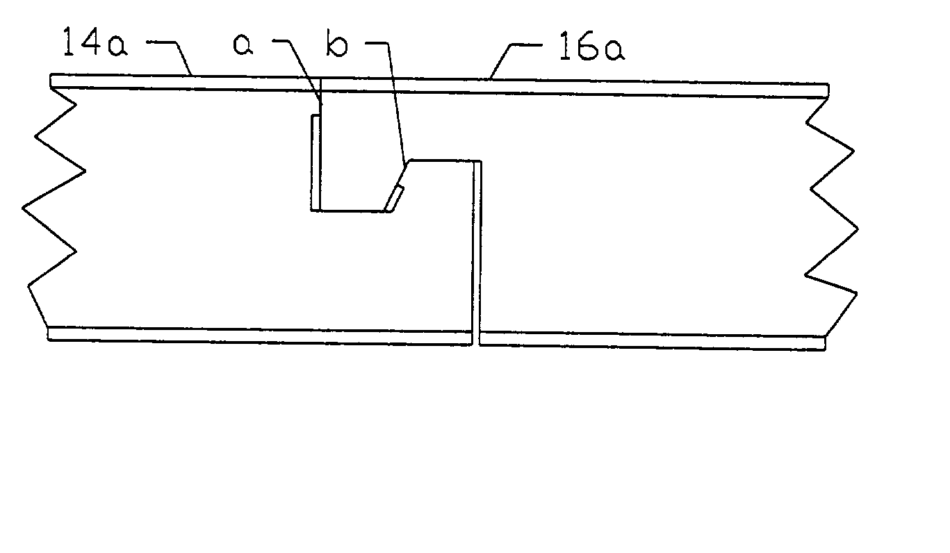
[0031] The present invention, as illustrated in FIGS. 2 and 3, provides panels 10 which can be interconnected to one another. In a specific embodiment, each panel can be identical to other panels. A panel 10 includes a top, a bottom, and joint elements along the sides of panel 10. A panel 10 has two forms of connecting means provided by joint elements that run along opposite edges of the same panel 10. According to the present invention, one form of connecting means is provided by a lateral motion limiting female joint element 14 and a lateral motion limiting male joint element 16. The other form of connecting means is provided by a tongue joint element 18 and a groove joint element 20. The joint elements may take the form of formations formed within the panel at manufacture. By providing different joint elements along opposite edges of the panel 10, the subject paneling system effectively achieves a system for connecting panels to one another in a quick and easy manner without the ...


PUM


Abstract

A paneling system is provided herein that concerns interconnecting panels with opposite connecting sides of substantially tongue in groove joint couplings and opposing adjacent connecting sides that are of substantially hook-joint coupling. The hook joint hinders lateral motion while permitting movement in a direction perpendicular to the plane of the interconnected panels to provide ease of installment and removal. The hook joints also provide proper alignment and spacing between panels.

Description

[0001] The subject invention relates to a method and apparatus for paneling. In a specific embodiment, the subject invention pertains to paneling used in the installation and disassembly of floor covering systems or wall panels.BACKGROUND OF INVENTION[0002] Floor panels having either substantially rectangular or square shapes can be installed in various ways. Generally, it is desirable to have a floor covering composed of panels positioned together to form tight fitting joints and an outer appearance devoid of large gaps or cracks. It is also desirable that the panels be easily and quickly assembled and disassembled to reduce installation time and costs. Previous techniques in assembling snap-together paneling systems involved careful planning in positioning and laying panels end to end to form an aesthetically pleasing covering. Once the panels were laid out and presented a desired covering, they were permanently attached to an underlying floor, either by means of gluing or nailing...

Claims


Application Information

Patent Timeline
Patent Type & Authority Applications(United States)
IPC IPC(8): E04F15/04
CPCE04F15/04E04F2201/028E04F2201/026E04F2201/0153E04F2201/0138
Inventor EVJEN, JOHN M.
Owner EVJEN JOHN M
Why Eureka
Try Eureka