Apparatus and method of object tracking

a technology of object tracking and apparatus, applied in the field of apparatus and method of object tracking, sports broadcasting, can solve problems such as ambiguity, and achieve the effect of reducing the cost and labor involved in marking up video footage to generate match statistics

Inactive Publication Date: 2009-03-05
SONY CORP
View PDF6 Cites 113 Cited by
  • Summary
  • Abstract
  • Description
  • Claims
  • Application Information

AI Technical Summary

Benefits of technology

[0011]Therefore, by logging object identification data associated with each object involved in an occlusion event so that the object identification data is associated with those objects involved in the occlusion event, and then identifying and updating logged path data that relates to the position of each object with respect to time, which records a path that each object has taken with respect to the three dimensional model of the plane, objects can be successfully tracked even though their identity may be ambiguous for a time period after an occlusion event. However, after the ambiguity has been resolved, the logged path data can be updated so that there is a record of which object is which. For example, in a football match where one player on a team passes behind a player on the same team, as seen from the view point of a video camera, their identities may become ambiguous. However, embodiments of the present invention allow both players to be tracked and their identities revised or updated if or when the identity of one or both of the players becomes known. Therefore, costs and labour involved in marking up video footage to generate match statistics can be reduced or match statistics can be generated automatically from the positions of the tracked players.

Problems solved by technology

As such, there can occur occlusion events in which one object obscures another object, so that there is some ambiguity between whether a track for either object thereafter is for one or the other of the objects.

Method used


Image

  • Apparatus and method of object tracking
  • Apparatus and method of object tracking
  • Apparatus and method of object tracking

Examples


example illustration

[0107]FIGS. 10, 11A, 11B and 12 provide example illustrations of frames of example video images of a football match in which the present technique has been used to track players and produce a 3D model of the football match as a virtual model. FIG. 10 provides an example illustration of a video image produced by one HD camera of a football match. FIG. 11A provides an illustration of the video image of FIG. 9 in which the image has been processed to produce the background only using the mean value of each pixel, and FIG. 11B provides an illustration of the video image of FIG. 9 in which the image has been processed to produce the background only using the variance of each pixel in the image. FIG. 12 provides an illustration of a result of the tracking which is to provide a bounded box around each player in correspondence with the example shown in FIG. 3A.

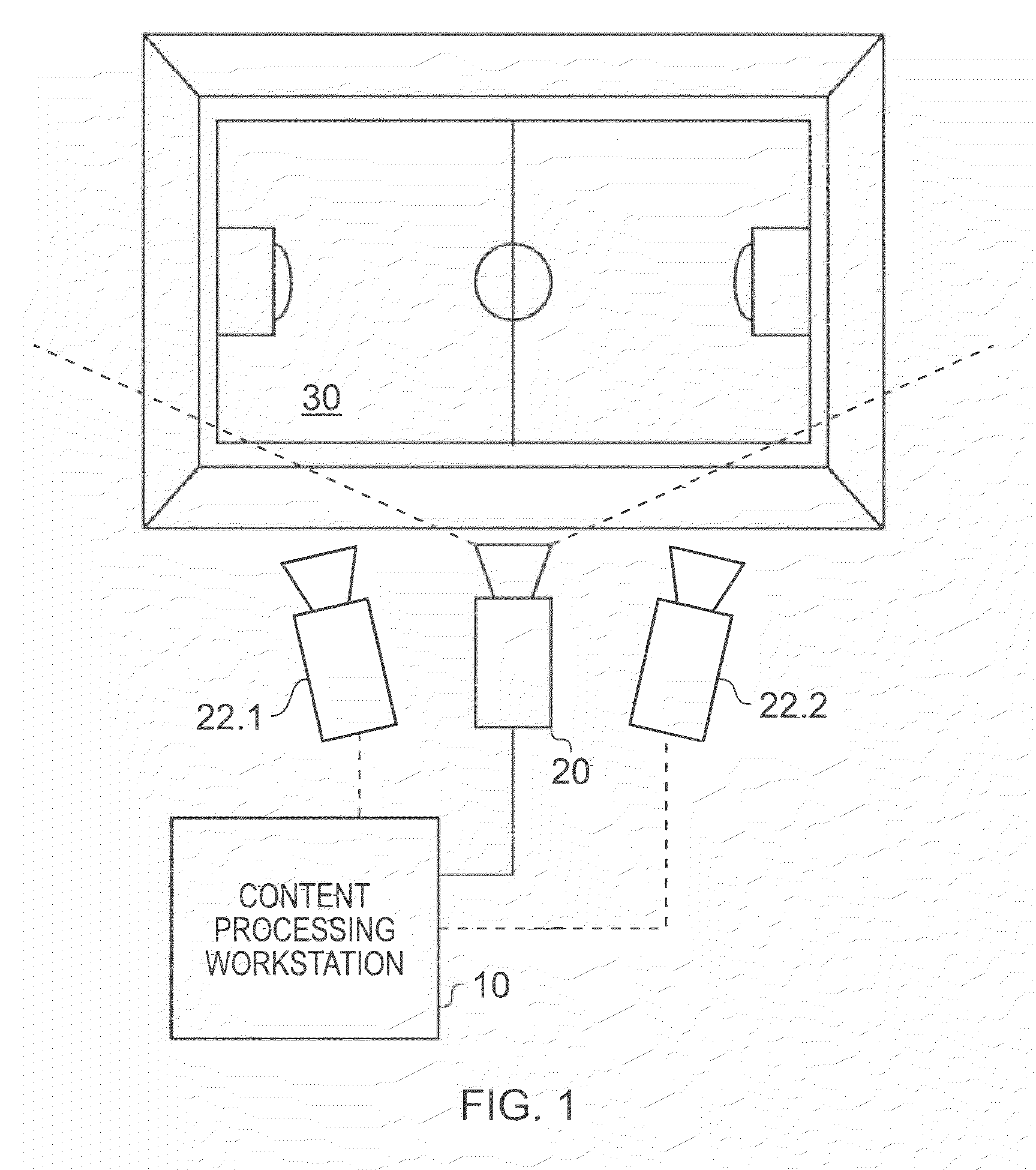
[0108]FIG. 13 provides a corresponding illustration in which two cameras have been used (such as the cameras 22.1, 22.2) to generate...


PUM


Abstract

A method of tracking objects on a plane within video images of the objects captured by a video camera. The method includes processing the captured video images so as to extract one or more image features from each object, detecting each of the objects from a relative position of the objects on the plane as viewed from the captured video images by comparing the one or more extracted image features associated with each object with sample image features from a predetermined set of possible example objects which the captured video images may contain; and generating object identification data for each object, from the comparing, which identifies the respective object on the plane. The method further includes generating a three dimensional model of the plane and logging, for each detected object, the object identification data for each object which identifies the respective object on the plane together with object path data. The object path provides a position of the object on the three dimensional model of the plane from the video images with respect to time and relates to the path that each object has taken within the video images. The logging includes detecting an occlusion event in dependence upon whether a first image feature associated with a first of the objects obscures a whole or part of at least a second image feature associated with at least a second of the objects; and, if an occlusion event is detected, associating the object identification data for the first object and the object identification data for the second object with the object path data for both the first object and the second object respectively and logging the associations. The logging further includes identifying at least one of the objects involved in the occlusion event in dependence upon a comparison between the one or more image features associated with that object and the sample image features from the predetermined set of possible example objects, and updating the logged path data after the identification of at least one of the objects so that the respective path data is associated with the respective identified object.

Description

CROSS REFERENCE TO PRIORITY APPLICATION[0001]The present application contains subject matter related to United Kingdom patent application number 0717277.8 filed in the United Kingdom Intellectual Property Office on Sep. 5, 2007, the entire contents of which being incorporated herein by reference.FIELD OF THE INVENTION[0002]The present invention relates to an apparatus and methods of tracking objects within video images of the objects captured by a video camera.BACKGROUND OF THE INVENTION[0003]In the field of sports broadcasting such as coverage of football matches, it is usual for commentators to identify visually players from live video footage of a match or from a vantage point in a stadium so that match statistics may be compiled about each player. Additionally, for highlights programs, information about a position of each player on a field of play and their actions on the field of play may be compiled by an operator from the recording of the live video footage using a suitable r...

Claims


Application Information

Patent Timeline
Patent Type & Authority Applications(United States)
IPC IPC(8): H04N7/18G06T17/00
CPCG06K9/00369G06K9/00711G06K2009/3291G06T7/2046G11B27/28G06T2207/30221G06T2207/30241G11B27/105G06T2207/10021G06T7/251G06V40/103G06V20/40G06V10/62G06T7/246G06T7/285G06T7/70G06T2207/20021
Inventor WAGG, DAVIDWILLIAMS, MICHAEL JOHN
Owner SONY CORP
Why Eureka
Try Eureka