Time measurement in a packet-switched communication network

a communication network and time measurement technology, applied in the field of communication networks, can solve the problems of not realizing the invalidity of the time measurement relating to the block period, and the inability to detect the error in the reception sequence,

Active Publication Date: 2017-08-24
TELECOM ITALIA SPA
View PDF2 Cites 15 Cited by
  • Summary
  • Abstract
  • Description
  • Claims
  • Application Information

AI Technical Summary

Benefits of technology

[0029]Preferably, in step b) the minimum inter-transmission time is set to a value suitable for preventing reception sequence errors involving overtaking between the first packets marked by the first marking value.
[0030]According to some variants, the minimum inter-transmission time is longer than an

Problems solved by technology

However, while packet loss affecting a block period may be detected (and the time measurements relating to that block period may accordingly be discarded as invalid), reception sequence errors may not be detected, since the receiving node bases identification of packets to be subjected to time measurement only on the packet count.
Hence, in case a reception sequence error occurs in a block period during which no packet loss occurred, and the error involves a packet to be subjected to time measurement, the receiving node can not detect the error and, accordingly, can not realize that the time measurements r

Method used


Image

  • Time measurement in a packet-switched communication network
  • Time measurement in a packet-switched communication network
  • Time measurement in a packet-switched communication network

Examples


Embodiment Construction

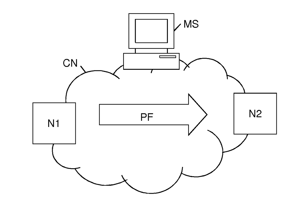
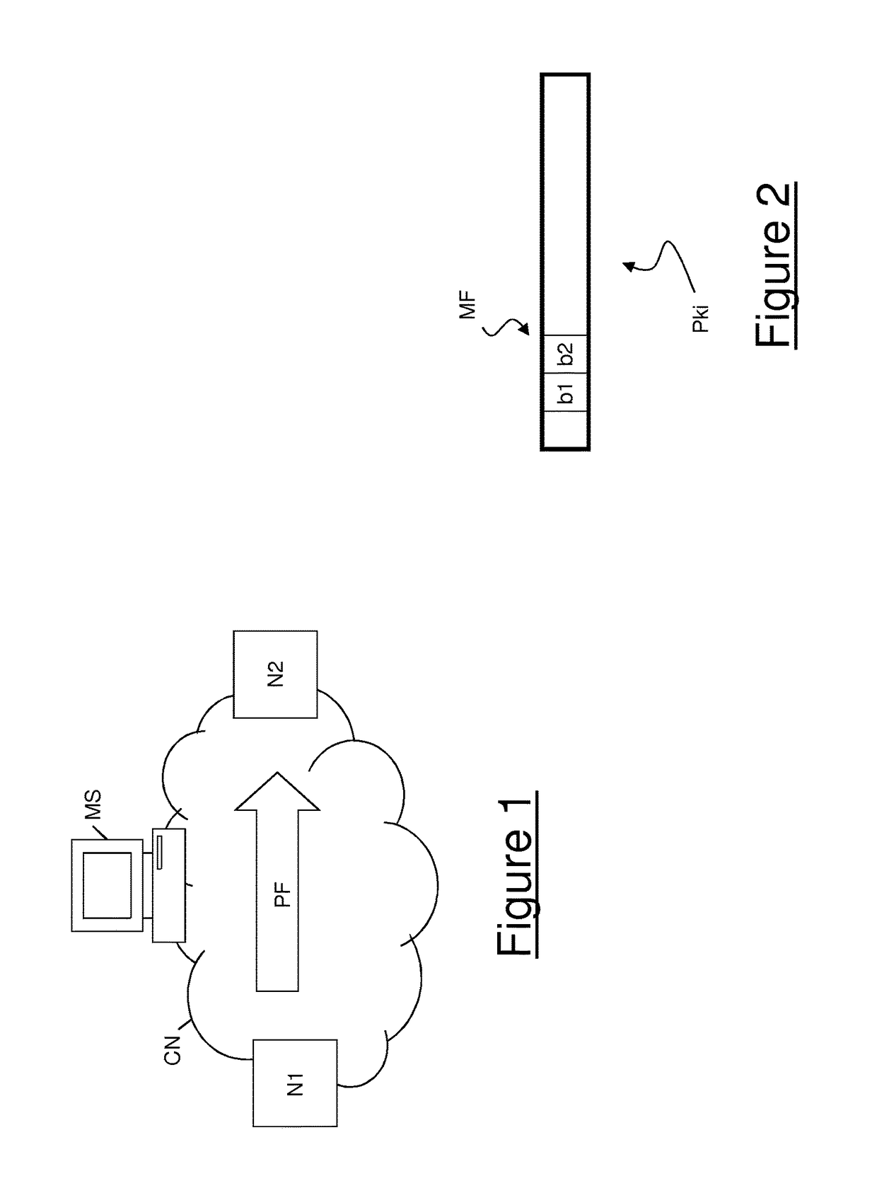
[0062]FIG. 1 schematically shows an exemplary packet-switched communication network CN in which the method for performing a time measurement according to embodiments of the present invention may be implemented. The communication network CN may be an IP network, an Ethernet network, an MPLS network or any other known type of packet-switched communication network.

[0063]The communication network CN comprises a plurality of nodes reciprocally interconnected by links according to any known topology.

[0064]In particular, the communication network CN comprises a first node N1 and a second node N2. The first node N1 (also termed herein after “transmitting node”) is configured to transmit a packet flow PF to the second node (also termed “receiving node”), possibly through intermediate nodes (not shown in FIG. 1) of the communication network CN. The transmitting node N1 may be either the source node of the packet flow PF or an intermediate node of the path from the source node to the destinati...


PUM


Abstract

It is disclosed a method for performing a time measurement on a packet flow transmitted through a communication network. The transmitting node divides the packets into first and second packets transmitted in alternating periods. At each period, transmitting node also marks each packet by setting a feature thereof to a first value indicating that the packet shall undergo time measurement or a second value indicating that the packet shall not undergo time measurement. The transmission times of two packets marked by the first value are reciprocally delayed by a predefined inter-transmission time shorter than a period duration. For each packet marked by the first value, the transmitting node generates a transmission time stamp and the receiving node generates a reception time stamp. Then, after the end of each period, a time measurement is performed based on transmission and reception timestamps of packets marked by the first value transmitted during the preceding period.

Description

TECHNICAL FIELD[0001]The present invention relates to the field of communication networks. In particular, the present invention relates to a method for performing a time measurement (in particular, a delay measurement and / or a jitter measurement) of a data flow (in particular, a packet flow) transmitted between two measurement points in a packet-switched communication network. Further, the present invention relates to nodes and computers for communication network configured to implement such a method, and to computer networks comprising such nodes and computers.BACKGROUND ART[0002]In a packet-switched communication network, data are transmitted in the form of packets that are routed from a source node to a destination node through possible intermediate nodes. Exemplary packet-switched networks are IP (Internet Protocol) networks, Ethernet networks and MPLS (Multi-Protocol Label Switching) networks.[0003]Packets not always reach the destination node, i.e. they may be lost during tran...

Claims


Application Information

Patent Timeline
IPC IPC(8): H04L12/26
CPCH04L43/0858H04L43/087H04L43/106H04L43/022H04L43/0852
Inventor COCIGLIO, MAURO
Owner TELECOM ITALIA SPA
Why Eureka
Try Eureka