Boom component display apparatus

a display apparatus and component technology, applied in the direction of load-engaging elements, safety gear, transportation and packaging, etc., can solve the problem of difficulty in preventing the unit boom from being connected in the wrong connecting sequen

Active Publication Date: 2010-10-12
KOBELCO CONSTR MASCH CO LTD
View PDF10 Cites 0 Cited by
  • Summary
  • Abstract
  • Description
  • Claims
  • Application Information

AI Technical Summary

Benefits of technology

[0006]The purpose of the present invention is to provide with a boom component display apparatus that makes it possible to prevent each unit boom from being connected in the wrong connecting sequences.
[0008]According to this configuration, as the connecting sequence information of the unit booms showing the relation between the connecting sequence and the identification information of a plurality of the unit booms forming a boom assembly is shown on the display unit, an operator can confirm the connecting sequence of the unit booms having the prescribed identification informations. Thus, the operator can easily judge whether the appropriate connecting sequence is conducted or not, accordingly the operator can prevent the unit booms from being connected in the wrong connecting sequence.
[0010]According to this configuration, as the processing units of the unit booms are connected electrically with each other successively from the side of the boom base section to the side of the boom top section by the power source connecting means, so the identification informations are sent to the display unit in the order beginning with the boom base section located next to the crane main body and ending up with the boom top section. Moreover the display unit can display the relation between the identification informations and the connecting sequence as the connecting sequence of the unit booms by using a receiving order of the identification informations. In this case, the simple configuration like this makes it possible to acquire the relation between the identification informations of the unit booms and the connecting sequence information of the corresponding unit boom.
[0012]According to this configuration, as the identification informations of a plurality of the unit booms are displayed in the same order as the connecting sequence of a plurality of the corresponding unit booms, it is easy to check the connecting sequence of the unit booms visually. Accordingly, an operator can easily judge whether the connecting sequence of the unit booms is properly arranged or not.
[0016]In this arrangement, since the reference connecting sequence information is displayed on the display unit, an operator can visually confirm the reference connecting sequence information and he can compare it with the actual connecting sequence information of the unit booms. Accordingly, by storing the relation showing the appropriate connecting sequence of the unit booms in the memory of the display unit as an appropriate connecting sequence, an operator can identify easily whether the connecting sequence of the unit booms is properly conducted or not.

Problems solved by technology

In this respect, it has been difficult to prevent the unit booms from being connected in the wrong connecting sequences.

Method used


Image

  • Boom component display apparatus
  • Boom component display apparatus
  • Boom component display apparatus

Examples


Embodiment Construction

[0026]Hereinafter, referring to the drawings, a description is given to preferred embodiments to carry out the present invention.

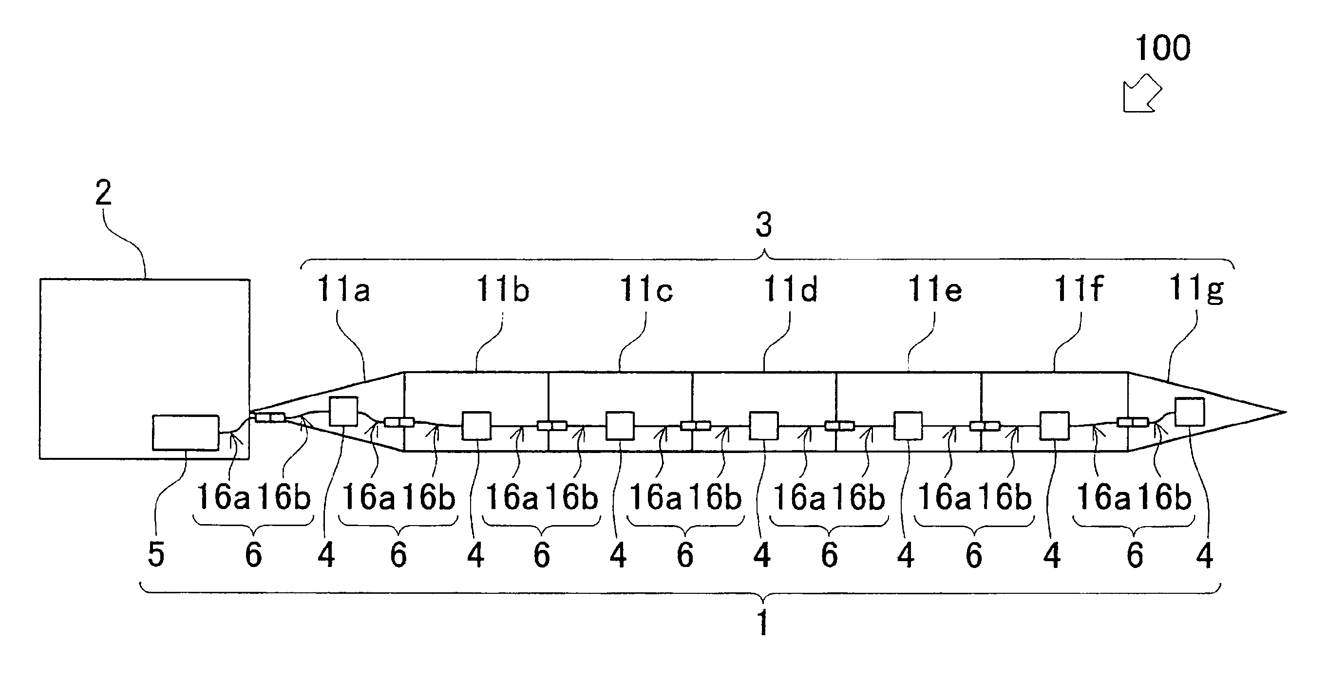
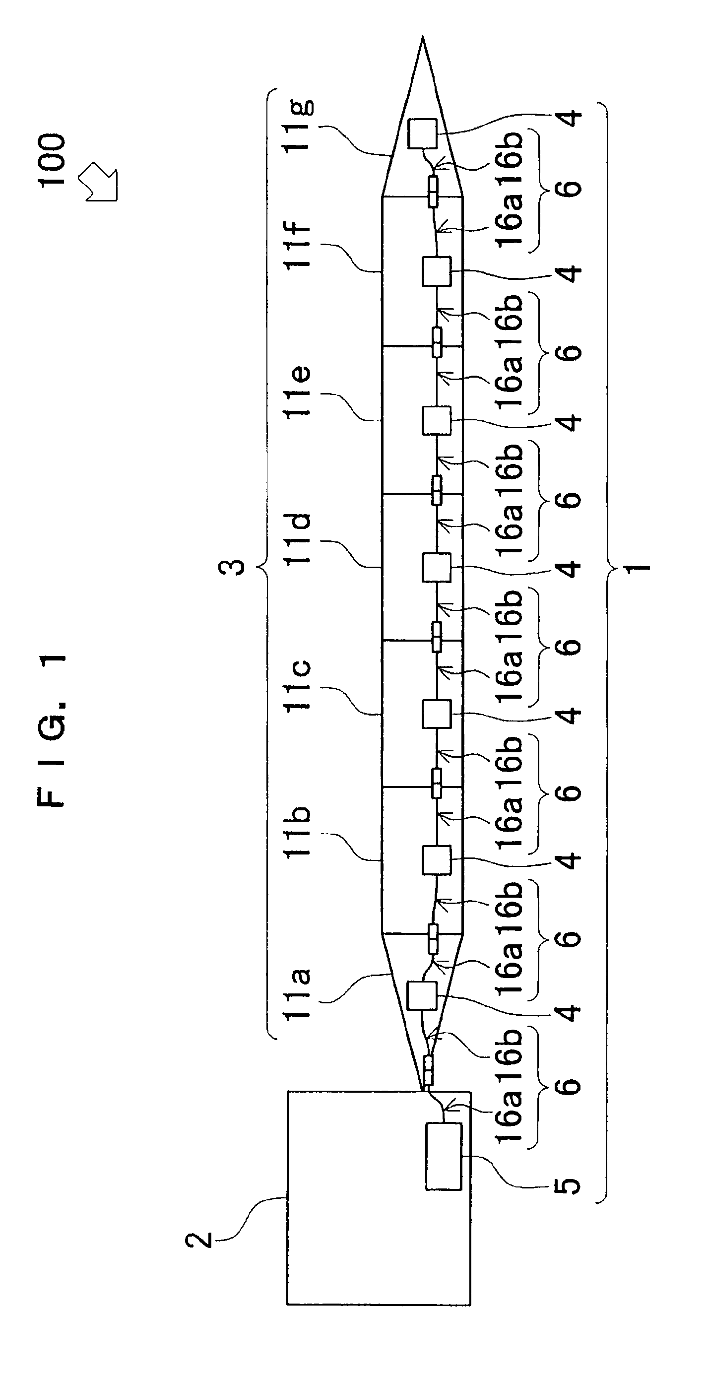
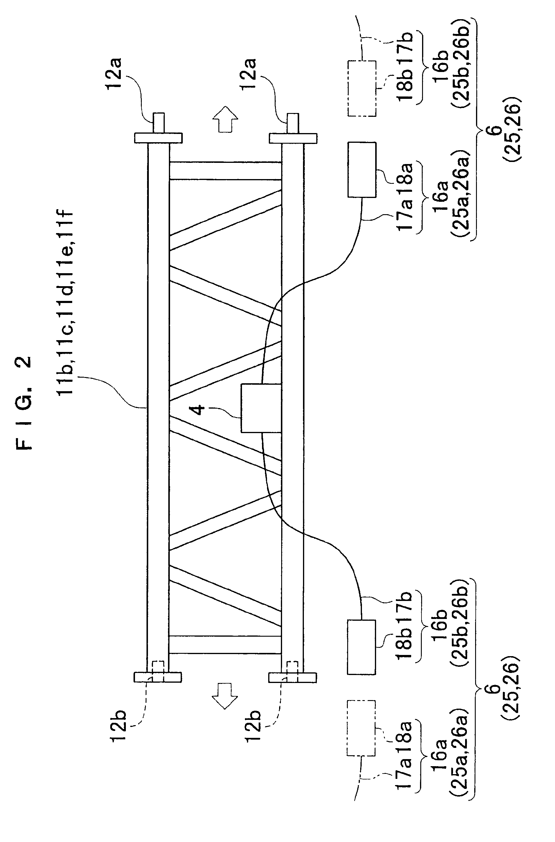
[0027]FIG. 1 shows an outline view of a configuration of a crane 100 to which a boom component display apparatus relating to the embodiment of the present invention is applied. FIG. 2 is a schematic view to explain a structure of the unit booms of the crane 100 shown in FIG. 1. FIG. 3 is a block diagram to explain a configuration of a processing unit 4 installed on each unit boom of the crane 100 shown in FIG. 1. FIG. 4 is a block diagram to explain a configuration of display unit 5 to be installed in a crane main body 2 shown in FIG. 1. First of all, referring to FIG. 1 thru FIG. 4, a description is given to the configuration of boom component display apparatus 1 relating to the embodiment of the present invention.

[0028]A crane 100 consists of a crane main body 2, a boom assembly 3 that is so arranged as to mount on the relevant crane main body 2 at its b...


PUM


Abstract

A boom component display apparatus 1 of the present invention is provided with processing units 4, connector assemblies 6 and a display unit 5. The processing units 4 are installed on each of a plurality of unit booms 11a thru 11g that compose a boom assembly 3 of a crane 100 and outputs identification information of each unit boom. The connector assemblies 6 transmits the identification information outputted from the processing units 4. The display unit 5 displays a connecting sequence information to show the relation between the connecting sequence of a plurality of unit booms 11a thru 11g and the identification information of a plurality of unit booms 11a thru 11g, basing on the identification information sent from the processing units 4 through the connector assemblies 6. By depending upon the boom component display apparatus of the present invention, it is possible to prevent the unit booms from being assembled in the wrong connecting sequences.

Description

BACKGROUND OF THE INVENTION[0001]1. Field of the Invention[0002]The present invention relates to a boom component display apparatus, in those cranes which are provided with such a boom assembly as formed by connecting a plurality of unit booms.[0003]2. Description of the Related Art[0004]Conventionally, such a crane that makes it possible for identification information of each unit boom to be transmitted to its crane main body is known. Such a conventional crane is provided with a processing unit that outputs the identification information of each unit boom, and a communication unit that transmits the identification information sent from the processing unit to a central processing unit that is located on the crane main body. The processing unit and the communication unit are installed on each unit boom respectively. With these arrangements provided, by adding up all unit booms' lengths included in the identification information and sent to the central processing unit, it is possible...

Claims


Application Information

Patent Timeline
Patent Type & Authority Patents(United States)
IPC IPC(8): B66C23/70
CPCB66C23/70B66C23/905
Inventor ISHIHARA, HIDEAKI
Owner KOBELCO CONSTR MASCH CO LTD
Why Eureka
Try Eureka