Liquid ejection apparatus and liquid ejection head

a liquid ejection apparatus and liquid ejection technology, applied in printing and other directions, can solve the problems of deteriorating image quality, fluctuation of dynamic pressure, color unevenness in formed images, etc., and achieve the effect of stably ejecting

Inactive Publication Date: 2017-11-30
CANON KK
View PDF3 Cites 5 Cited by
  • Summary
  • Abstract
  • Description
  • Claims
  • Application Information

AI Technical Summary

Benefits of technology

[0008]An object of the present invention is to provide a liquid ejection apparatus and a liquid ejection head that allows suppression of a fluctuation in the pressure of a liquid in a flow path caused by a liquid delivery unit, enabling the liquid to be stably ejected through ejection ports.

Problems solved by technology

Liquid ejection apparatuses that eject a liquid such as ink for printing are known to suffer the following problems in a case where the position of meniscus in each ejection port fluctuates.
The amount of droplets ejected through the ejection ports varies, leading to color unevenness in a formed image.
This varies landing accuracy for droplets landing on the print medium, deteriorating image quality.
A cause of these problems is a fluctuation in a dynamic pressure (pressure loss) in a liquid supply flow path.
This in turn fluctuates the position of meniscus in each ejection port, leading to the likelihood of problems as described in 1) and 2).
However, the technique disclosed in Japanese Patent No. 3606282 needs a complicated mechanism to actuate the valve, disadvantageously resulting in increased costs.

Method used


Image

  • Liquid ejection apparatus and liquid ejection head
  • Liquid ejection apparatus and liquid ejection head
  • Liquid ejection apparatus and liquid ejection head

Examples


first embodiment

[0026]FIGS. 1 to 7 are diagrams depicting a first embodiment of a liquid ejection apparatus according to the present invention. In the present embodiment, as the liquid ejection apparatus, an ink jet printing apparatus (hereinafter simply referred to as a printing apparatus) that ejects ink onto a print medium to form an image thereon will be described by way of example. The ink as used herein includes not only a liquid containing a coloring material used to form an image on a print medium but also a treatment liquid intended to improve fixability and weatherability of the image formed on the print medium.

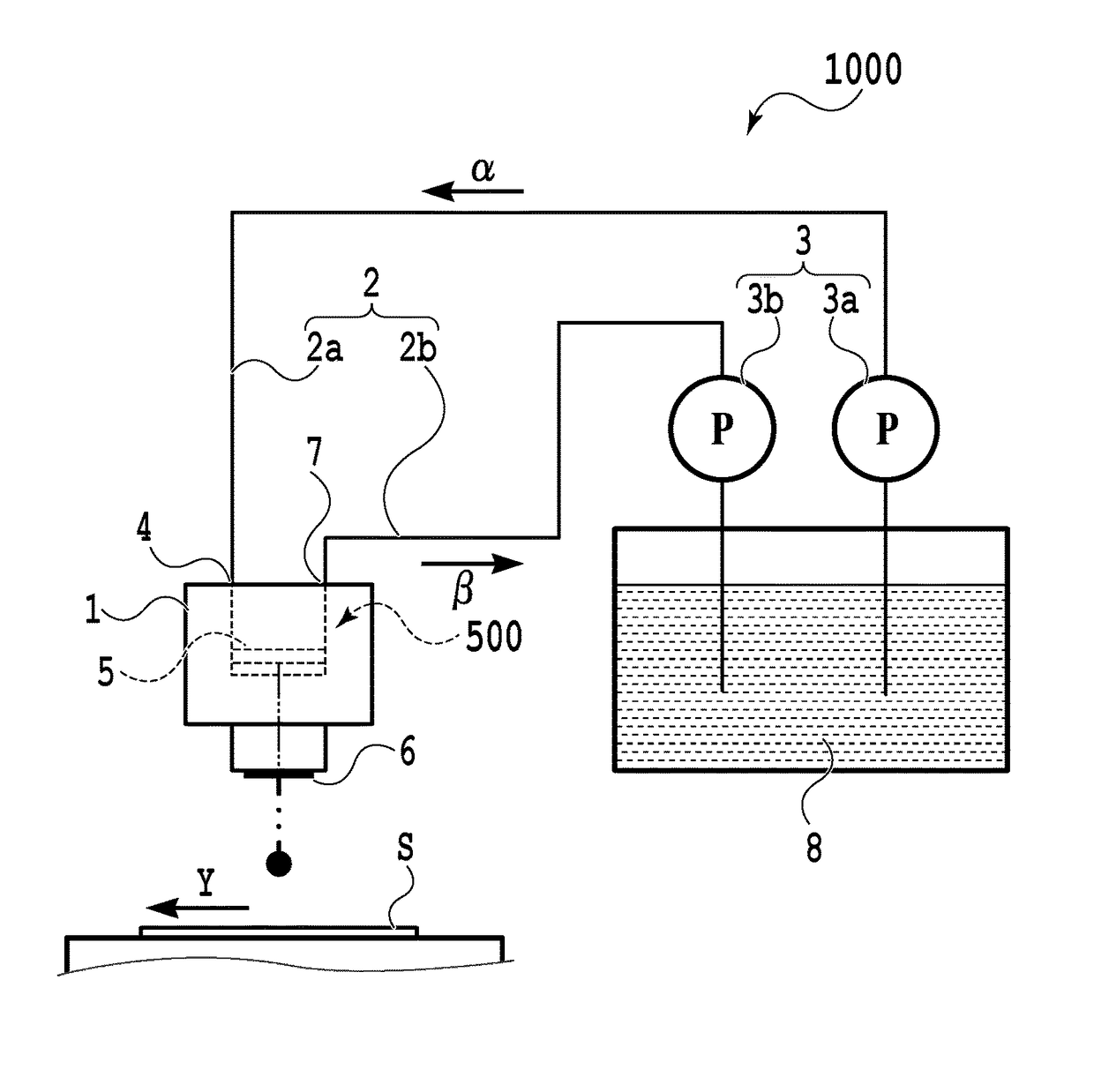
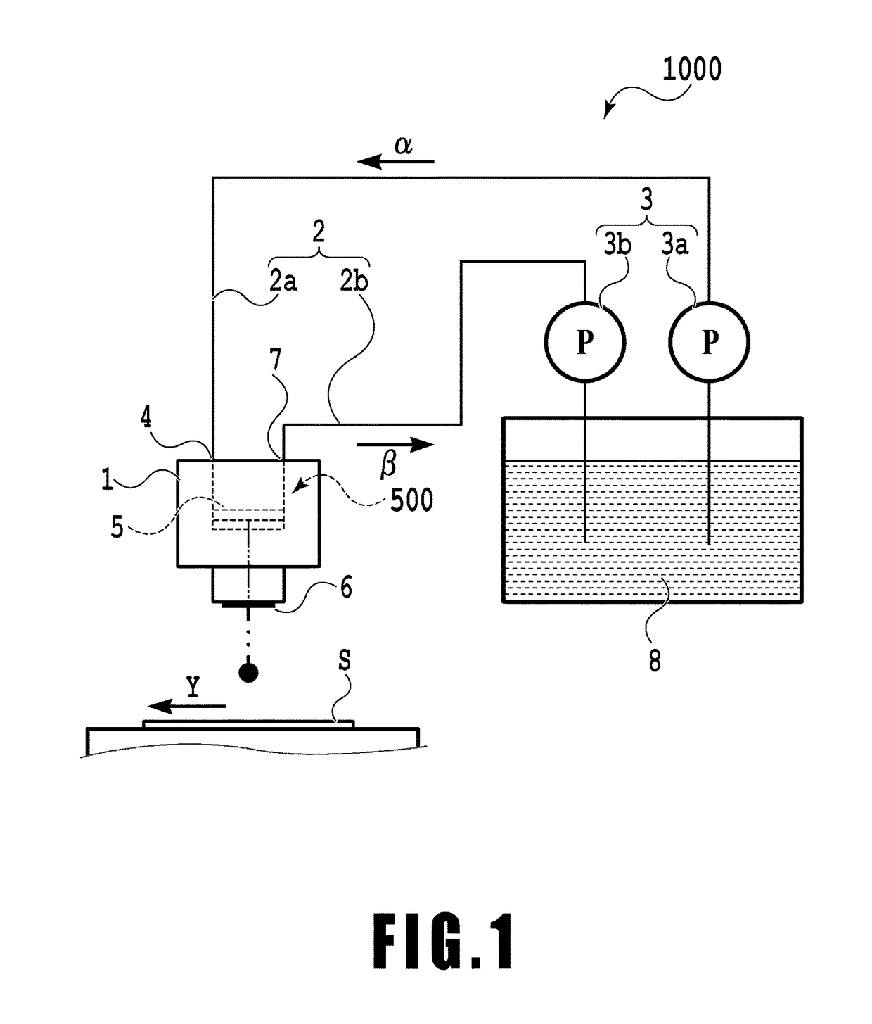
[0027]FIG. 1 is a schematic diagram depicting a basic configuration of a printing apparatus 1000 in the present embodiment. The printing apparatus 1000 includes a liquid ejection head 1 and a liquid storage 8 that stores ink to be fed to the liquid ejection head 1. The printing apparatus 1000 further includes an extra-head flow path 2 that couples the liquid storage 8 and the liqui...

second embodiment

[0074]Now, a second embodiment of the present invention will be described with reference to FIGS. 9A to 9C. FIGS. 9A to 9C are schematic diagrams depicting the printing element 11 and components around the ejection port. FIG. 9A illustrates a state before ink ejection, FIG. 9B illustrates a state during ink ejection, and FIG. 9C illustrates a state after ink ejection.

[0075]The present embodiment has an efficient configuration in which 70% or more, that is, substantially all of ink (liquid) 13 on an energy generating element in the pressure chamber changes to an ink droplet (droplet) 14a, which is then ejected. To allow an ink droplet to be ejected in a larger ejection volume from such a liquid ejection head, the diameter of each ejection port needs to be further increased. However, an increased diameter of the ejection port causes the meniscus in the ejection port to be more significantly displaced in response to a fluctuation in pressure. As a result, the ejection volume fluctuatio...

third embodiment

[0077]Now, a third embodiment of the present invention will be described.

[0078]In the first embodiment, an example has been illustrated where the indicator for the intra-head flow path 100 is equal to or smaller than 1 (√(ω / 2ν)×a≦1) and where the radially enlarged component serving to set the indicator larger than 1 is formed at least in a part of the extra-head flow path 2. In contrast, in the third embodiment, the indicator for the intra-head flow path 100 formed in the liquid ejection head is designed to be larger than 1.

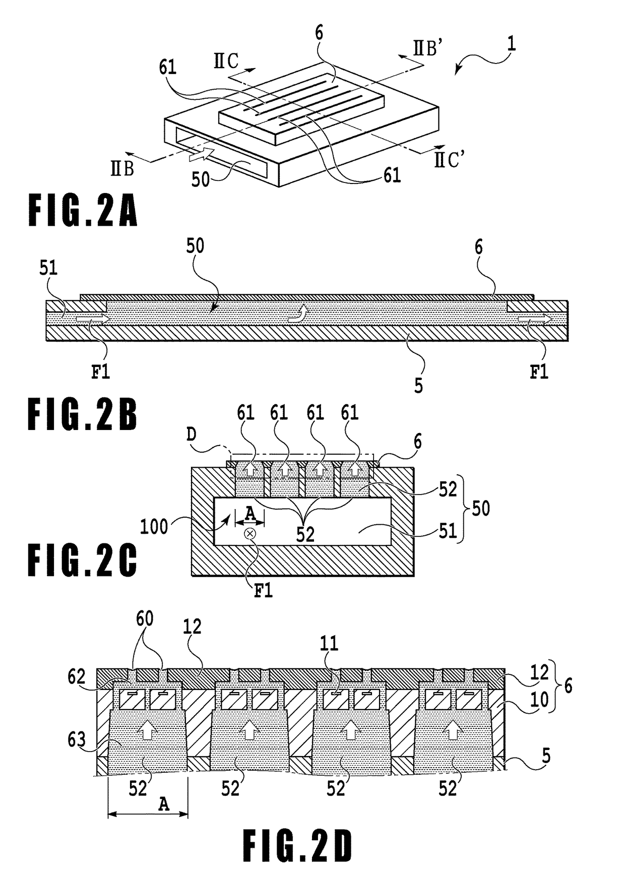
[0079]FIGS. 10A to 10D are diagrams depicting a configuration of a liquid ejection head 200 in the third embodiment. FIG. 10A is a perspective view. FIG. 10B is a sectional view taken along line XB-XB′ in FIG. 10A, and FIG. 10C is a sectional view taken along line XC-XC′ in FIG. 10A. Components in FIGS. 10A to 10D that are the same as or correspond to particular components of the liquid ejection head 1 depicted in FIGS. 2A and 2B are denoted by the same reference...


PUM


Abstract

An object is to provide a liquid ejection apparatus that allows suppression of a fluctuation in a pressure of a liquid in a flow path caused by a liquid delivery unit, enabling the liquid to be stably ejected through an ejection port. The liquid ejection apparatus including a liquid ejection head having an ejection port through which a liquid is ejected, a flow path configured to communicate with the ejection port, and a liquid delivery unit configured to feed the liquid to the flow path. A relation between an angular frequency ω of the liquid delivered from the liquid delivery unit, a coefficient of kinematic viscosity ν of the liquid, and an equal diameter a of at least a part of a section of an extra-head flow path in a direction normal to a direction in which ink flows satisfies √(ω/2ν)×a>1.

Description

BACKGROUND OF THE INVENTIONField of the Invention[0001]The present invention relates to a liquid ejection apparatus that ejects a liquid through ejection ports in a liquid ejection head for printing, and to the liquid ejection head.Description of the Related Art[0002]Liquid ejection apparatuses that eject a liquid such as ink for printing are known to suffer the following problems in a case where the position of meniscus in each ejection port fluctuates.[0003]The amount of droplets ejected through the ejection ports varies, leading to color unevenness in a formed image.[0004]The speed of droplets ejected through the ejection ports (ejection speed) varies with respect to the moving speed of a print medium relative to the ejection ports. This varies landing accuracy for droplets landing on the print medium, deteriorating image quality.[0005]A cause of these problems is a fluctuation in a dynamic pressure (pressure loss) in a liquid supply flow path. For example, in a case where a liqu...

Claims


Application Information

Patent Timeline
Patent Type & Authority Applications(United States)
IPC IPC(8): B41J2/175
CPCB41J2/17553B41J2/14016B41J2/175B41J2/17596B41J2/18B41J2/045B41J2/14032B41J2/145
Inventor NAKAGAWA, YOSHIYUKI
Owner CANON KK
Why Eureka
Try Eureka