Ventilation fan with lamp

a technology of ventilation fan and lamp, which is applied in ventilation systems, heating types, lighting support devices, etc., can solve the problems of limited applicability and only the ventilation function of fans, and achieve the effect of blocking the noise generated by the fan module in operation, enhancing flexibility and freedom degree of installation of ventilation fans, and enhancing the appearance of ventilation fans

Inactive Publication Date: 2018-03-08
DELTA ELECTRONICS INC
View PDF7 Cites 17 Cited by
  • Summary
  • Abstract
  • Description
  • Claims
  • Application Information

AI Technical Summary

Benefits of technology

[0043]As mentioned above, the ventilation fan with lamp of this disclosure is installed to the ceiling having an installing opening. The ventilation fan includes a housing, a fan module, and a lamp module. The housing has a top plate and a side wall. The top plate and the side wall are connected with each other and form a third opening. The third opening connects to the installing opening. The fan module is accommodated in the housing. The lamp module is disposed out of the installing opening, and the lamp module and the housing are located at opposite sides of the ceiling. The lamp module can further block the noise generated by the fan module in operation. Besides, the internal structure of the ventilation fan cannot be viewed by the user directly, so that the appearance of the ventilation fan becomes more elegant. Since the lamp module is integrated in the ventilation fan, it can be fit to various environments so the flexibility and freedom degree for installing the ventilation fan are enhanced. Moreover, this disclosure can reduce the required installation space of the ceiling so as to increase the utility rate of the space. Since the lamp module and the third opening are disposed at opposite sides of the ceiling, the ventilation fan can have large inlet quantity and good air-exchange efficiency.

Problems solved by technology

However, the conventional ventilation fan only has the ventilation function, and the applicability thereof is thus limited.

Method used


Image

  • Ventilation fan with lamp
  • Ventilation fan with lamp
  • Ventilation fan with lamp

Examples


first embodiment

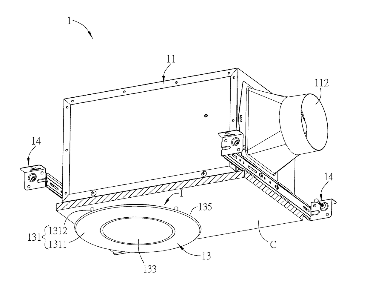
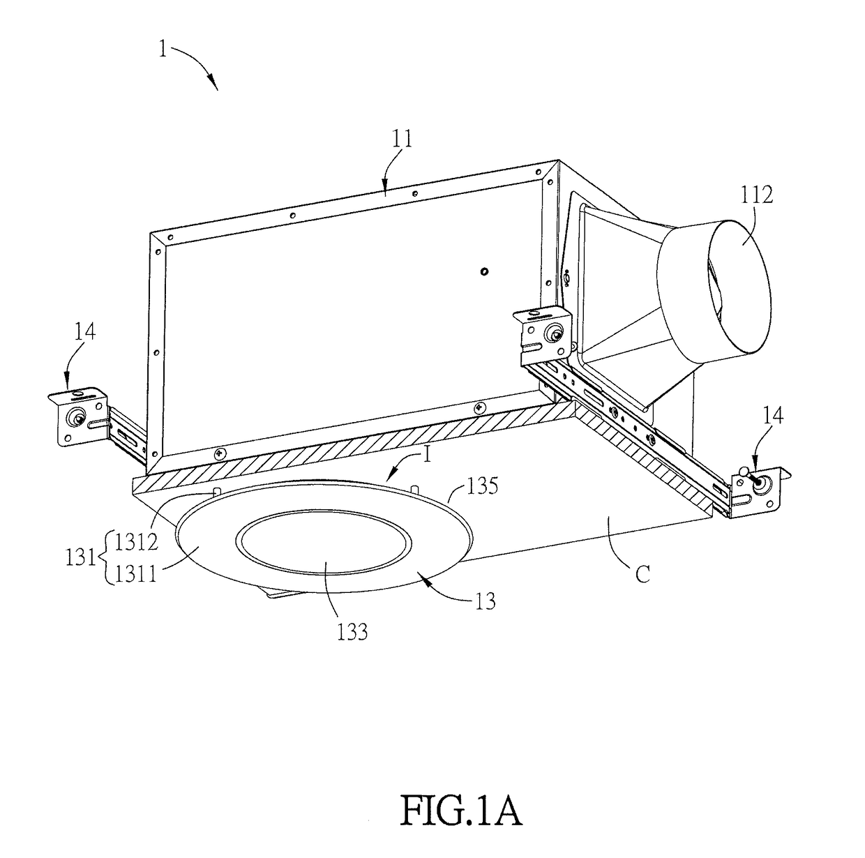
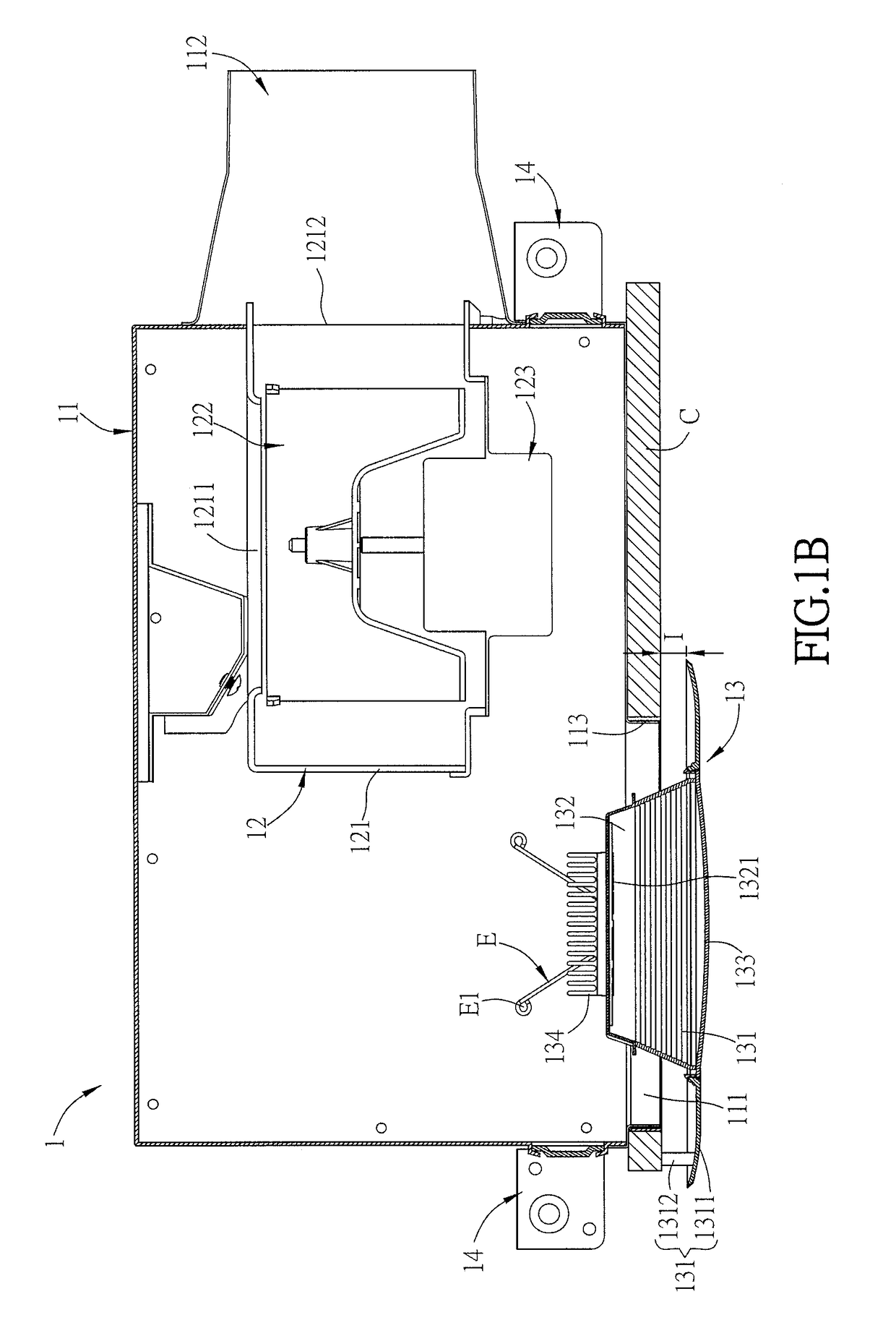
[0065]FIG. 1A is a schematic diagram of a ventilation fan with lamp of the invention, FIG. 1B is a sectional diagram of the ventilation fan in FIG. 1A, and FIG. 1C is an exploded diagram of the ventilation fan in FIG. 1A. As shown in FIGS. 1A, 1B, 1C, the ventilation fan with lamp 1 (abbreviated to the ventilation fan 1 hereinafter) is installed to a ceiling C including an installation opening C1. For the clarity of the figure to facilitate the illustration of the ventilation fan of this embodiment, only a part of the ceiling is shown. Herein, the ventilation fan 1 includes a housing 11, a fan module 12 and a lamp module 13. Moreover, the ventilation fan 1 of this embodiment further includes two installation brackets 14, which can be connected to the housing 11 and ceiling C by screwing, for example, to fix the housing 11 to the ceiling C. However, this invention is not limited thereto.

[0066]In this embodiment, the housing 11 is approximately a six-sided box structure and includes a...

second embodiment

[0076]FIG. 3C is a schematic sectional diagram of a ventilation fan of another embodiment of the invention. As shown in FIG. 3C, this embodiment is approximately the same as the above second embodiment, and the main difference therebetween is that the lens 133a is disposed between the lamp cover 131 and the base 132 and inside the housing 11. Certainly, the lens 133a also can be disposed at the first opening 111 so that a part of the lens 133a is disposed inside the housing and another part of the lens 133a is exposed from the housing 11.

[0077]FIG. 4 is a schematic sectional diagram of a ventilation fan with lamp of the third embodiment of the invention. As shown in FIG. 4, the ventilation fan 1b of this embodiment is approximately the same as the first embodiment, and the main difference therebetween is that the size of the housing 11a of this embodiment is less than that of the housing 11 of the above embodiment so that at least half volume of the fan module 12 is on the projectio...

fourth embodiment

[0079]FIG. 5A is a schematic diagram of a ventilation fan with lamp of the invention; FIG. 5B is an exploded view of the ventilation fan of FIG. 5A, FIG. 5C is an exploded view of the ventilation fan of FIG. 5A with a variation, and FIG. 5D is a sectional diagram of the ventilation fan of FIG. 5A.

[0080]As shown in FIGS. 5A to 5D, the ventilation fan 2 / 2a is installed to the ceiling C, and the ceiling C has an installing opening C2. To be noted, only a part of the ceiling C is shown in the figures for making the drawings more clear. In this embodiment, the ventilation fan 2 includes a housing 21, a fan module 22, and a lamp module 23. In addition, the ventilation fan 2 further includes a support 25 for installing with the installation holes (not shown) of the housing 21. The housing 21 can be connected to and fixed to the ceiling C by, for example but not limited to, screws.

[0081]In this embodiment, the housing 21 is roughly a rectangular box and has a top plate 218 and a side wall 2...


PUM


Abstract

A ventilation fan with lamp is installed to the ceiling having an installing opening. The ventilation fan includes a housing, a fan module, and a lamp module. The housing has a top plate and a side wall. The top plate and the side wall are connected with each other and form a first opening. The first opening connects to the installing opening. The fan module is accommodated in the housing. The lamp module is disposed out of the installing opening, and the lamp module and the housing are located at opposite sides of the ceiling.

Description

CROSS REFERENCE TO RELATED APPLICATIONS[0001]This application is a Continuation-In-Part (CIP) of an earlier filed, pending, application, having application Ser. No. 14 / 616,126 and filed on Feb. 6, 2015, the content of which, including drawings, is expressly incorporated by reference herein.BACKGROUND OF THE INVENTIONField of Invention[0002]The invention relates to a ventilation fan and, in particular, to a ventilation fan with lamp.Related Art[0003]For the sake of blocking the outdoor noise and heat and remaining the indoor temperature, the buildings are usually constructed by special materials to create unventilated rooms. Accordingly, a proper ventilation mechanism is required to exhaust the harmful contaminations.[0004]In order to improve the air convection in the rooms, many buildings are equipped with ventilation fans for supplying the fresh air. However, the conventional ventilation fan only has the ventilation function, and the applicability thereof is thus limited.SUMMARY OF...

Claims


Application Information

Patent Timeline
Patent Type & Authority Applications(United States)
IPC IPC(8): F21V33/00F04D29/28F04D29/00F04D25/08F21S8/02
CPCF21V33/0096F04D29/282F04D29/005F04D25/088F21S8/026F21W2131/30F04D29/4226F04D29/602F21V21/041F24F7/007F24F2221/02F21V29/74F21Y2115/10
Inventor HUANG, YU-HSIANGLIN, CHIH-HUA
Owner DELTA ELECTRONICS INC
Why Eureka
Try Eureka